If you find my tutorials helpful, you can support CADCAMLessons:
https://ko-fi.com/cadcamlessons
Tool entry into material in 2D Pocket strategy – Fusion 360
The next options for entering the tool into the material are Zig-zag, Profile, Smooth Profile and Helix. In each of these types we have the same parameters that we can control the entry of the tool into the material.

Let’s check what will be the differences between these methods of entering the tool into the material using the same parameters (such as in the figure above).
The Zig-zag option will give us the following results.

Using the Profile option, we get something like:

Using the Smooth Profile option, we’ll get:

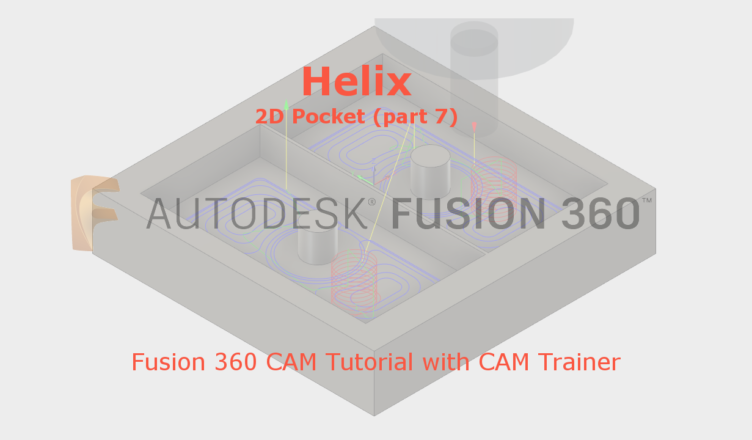
And using the Helix option, we’ll get:

Similar effect as in the case of the Smooth profile option.
Let’s check what the particular parameters correspond to.
The parameter Ramping Angle (deg) is responsible for the angle of entry of the tool into the material. In the above figure we have Ramping Angle = 2, and on the following Ramping Angle = 10.

We see that the angle has already increased and the tool more aggressively enters the material. Of course, in each of the above options, this parameter work the same.
Another option is Maximum Ramp Stepdown. This option specifies the maximum step down per helix revolution, i.e. something like the helix pitch.
In the above figure, where the parameter Ramping Angle = 10, the parameter Maximum Ramp Stepdown = 25. Let’s set the Maximum Ramp Stepdown = 2.

We can see that the input of the tool into the material is quite gentle and the tool is less loaded than in the previous example. Simply, for one turn of the helix the tool goes down 2 mm into the material.
The next parameter is Ramp Clearance Height, which is the height from which the tool will start helix machining (or profile or zigzag).
Ramp Clearance Height = 2.5 mm

Ramp Clearance Height = 10 mm

The Ramp Radial Clearance parameter specifies the minimum distance from the contour for the tool entry into the material. So if we set Ramp Radial Clearance = 10, the tool will enter the material at a distance of 10 (or more) mm from the contour of the pocket.
The Helical Ramp Diameter option specifies the maximum diameter of the helix at which the tool goes into the material.
The Minimum Ramp Diameter option specifies the minimum helix diameter at which the tool goes into the material.
The maximum value of the diameter of the helix should not be greater than twice the diameter of the tool, because the center may leave an unmachined.
The diameter of the helix will be chosen depending on the possibilities, on how much space there will be for the tool entry into the material.
The minimum value of the diameter of the helix will protect us against situations in which the tool will have, for example, the possibility of entering the helix with a diameter of, for example, 1 mm for the 12 mm diameter tool… This is not a good situation.
At the end we have a section of Positions, which allows us to determine the entry point of the tool in the material.
This will be especially useful when using the pre-hole.

To indicate, for example, the initial hole, click left mouse button on the Nothing field in the Predrill Positions and indicate the location of the pre-hole on the geometry. If the hole is inside the workpiece geometry, the tool starts machining at this point.
The situation with the Entry Positions option looks similar.

