CYCLE 232 Heidenhain – Face milling cycle
YouTube: https://youtu.be/wnqqTW5AlS4
CYCLE 232 Heidenhain is the face milling operation.
Heidenhain has a large number of implemented cycles that make it much easier to write programs.
In the previous lesson we defined and called the tool and prepare the first move to Z+50. The tool will start machining from here.
Next, we have to define NC code for tool movements. We can write the code line by line or use cycles. For face milling operation we will use a cycle.
First, we have to define the cycle.
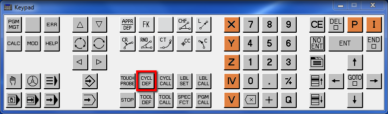
Press CYCL DEF button.
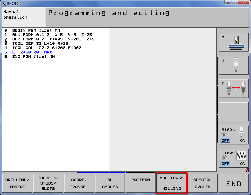
Select the MULTIPASS MILLING softkey.
And select the 232 cycle softkey.

We have several options to define here.
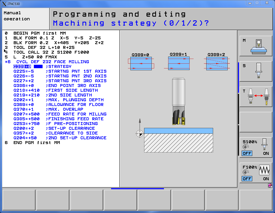
The first option is the machining method. Way of arranging the toolpaths.
We can choose one of three ways.
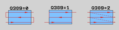
Select option 0. Press 0 and press ENT button.
Next option is the Starting point in the first axis. This is the X coordinate of the left lower corner.
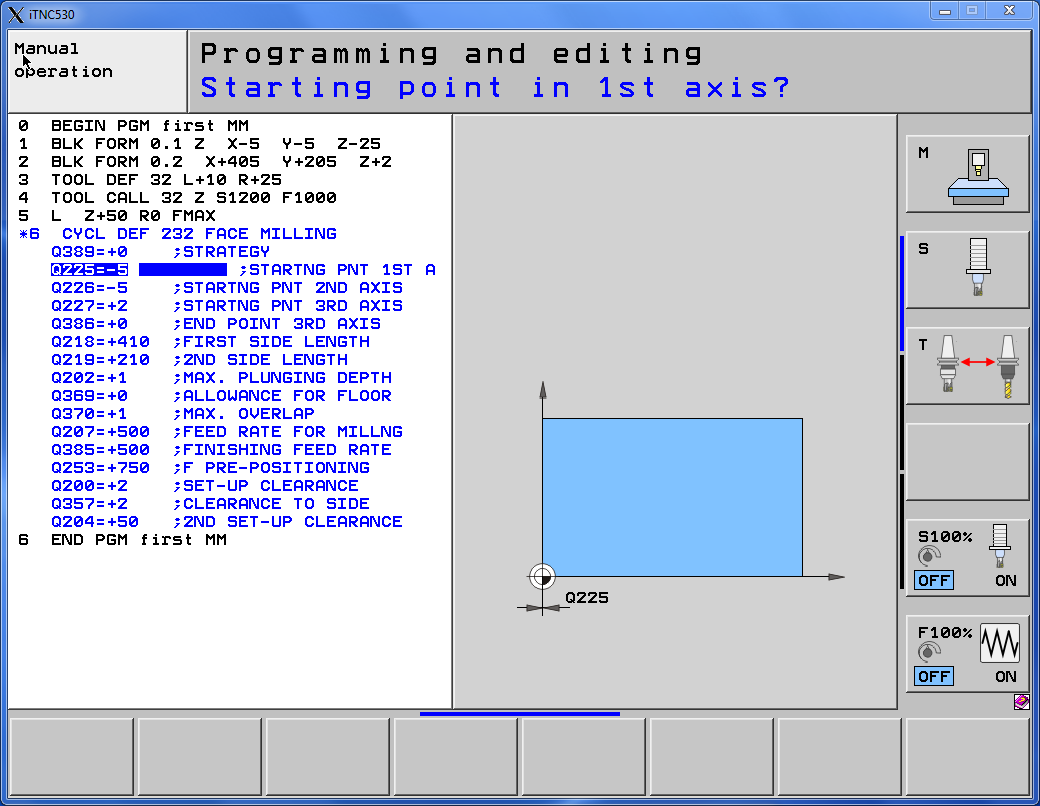
Enter -5 value and press ENT button.
Next option is the Starting point in the second axis. This is the Y coordinate of the left lower corner.
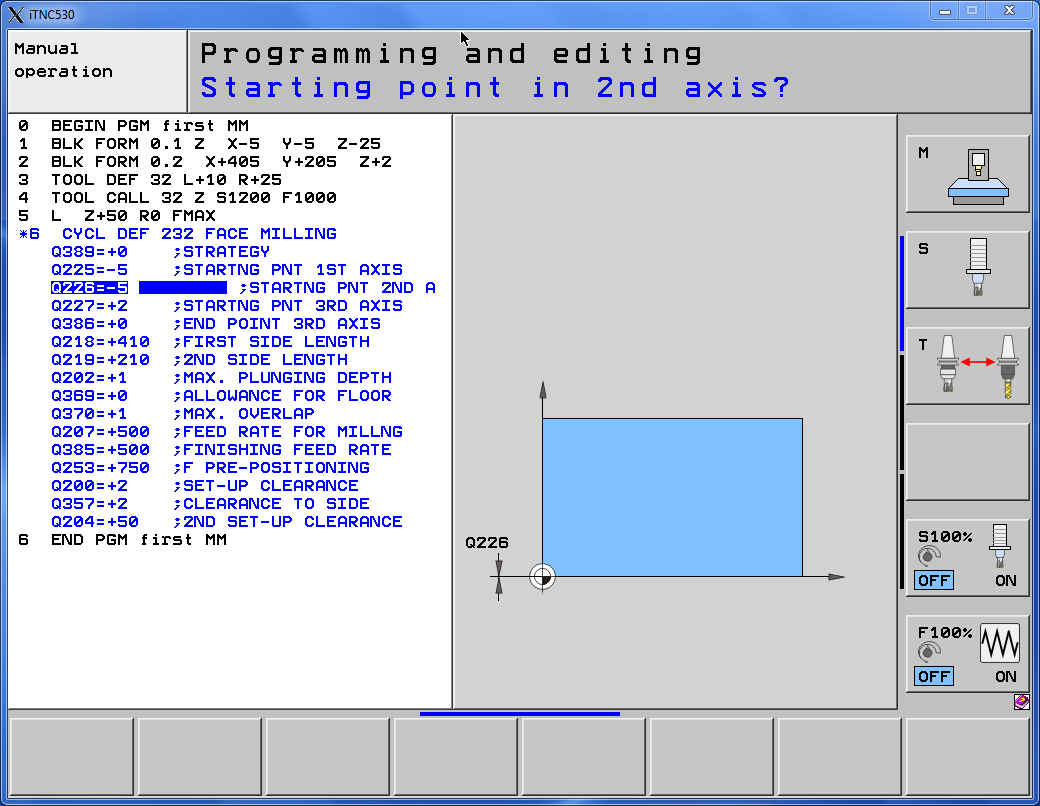
Enter -5 value and press ENT button.
Next option is the Starting point in the third axis. This is the Z coordinate of the left lower corner.
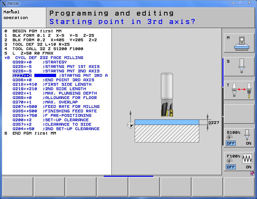
Enter 2 value and press ENT button.
Next option is the End point in the third axis. This is the Z coordinate of the top of material.

We have 2 mm of the allowance and we want to machine this material to Z0.
Enter 0 value and press ENT button.
Next option is the First side length. This is the incremental value and using + or – sign we can specify the direction of the machining.
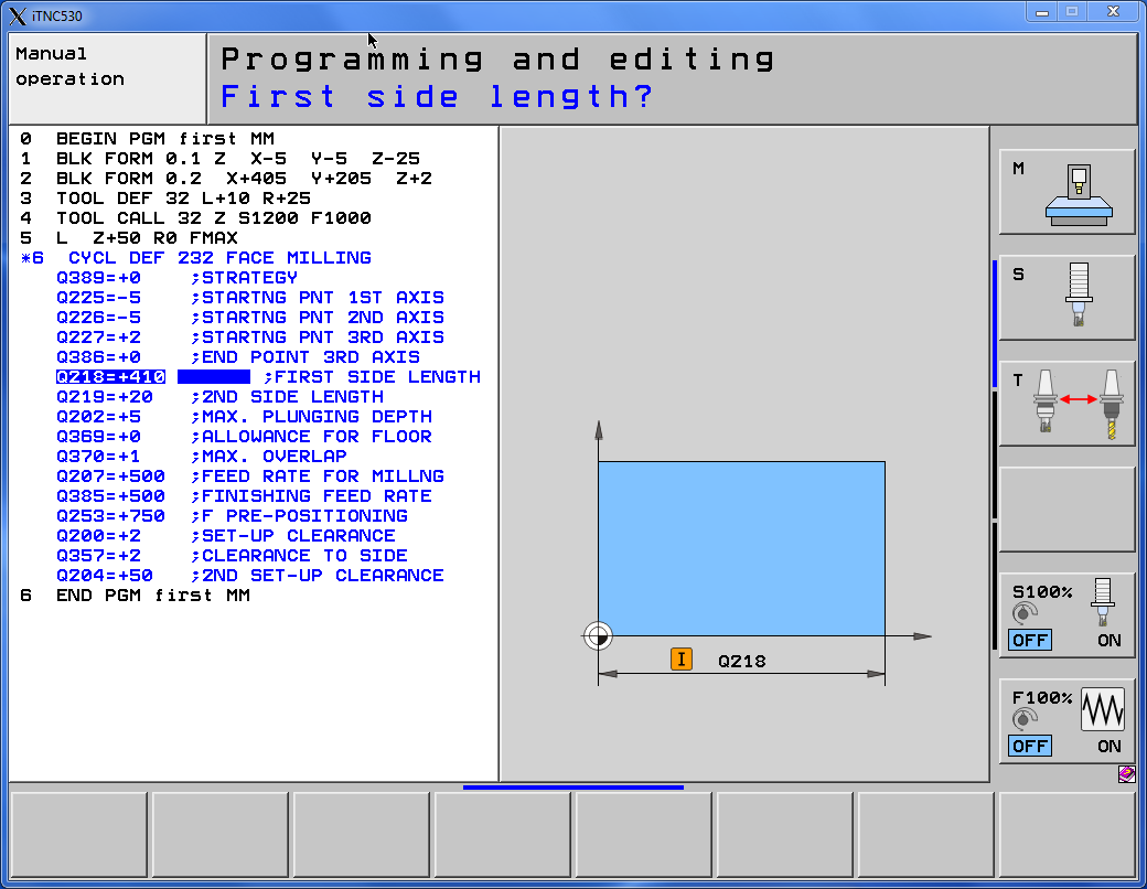
Enter +410 and press ENT button.
Next option is the Second side length. This is the incremental value and using + or – sign we can specify the direction of the machining.
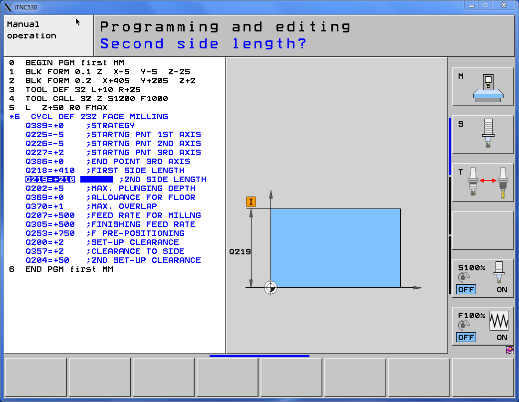
Enter +210 and press ENT button.
Next option is the Maximum plunging depth. This is the depth of one pass in the Z axis.
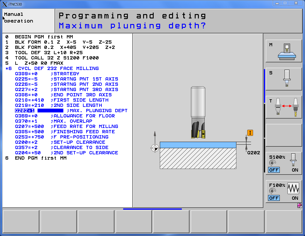
Enter 1 and press ENT.
Next option is the Allowance for floor. It is an allowance that will remain after machining.
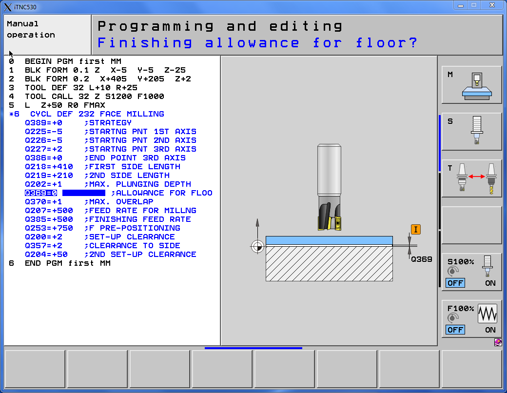
Enter 0 and press ENT.
Next option is the Maximum Overlap. This is the parameter responsible for the overlapping of subsequent tool passes. It is tool radius factor. Maximum overlap = Q369 * tool radius.
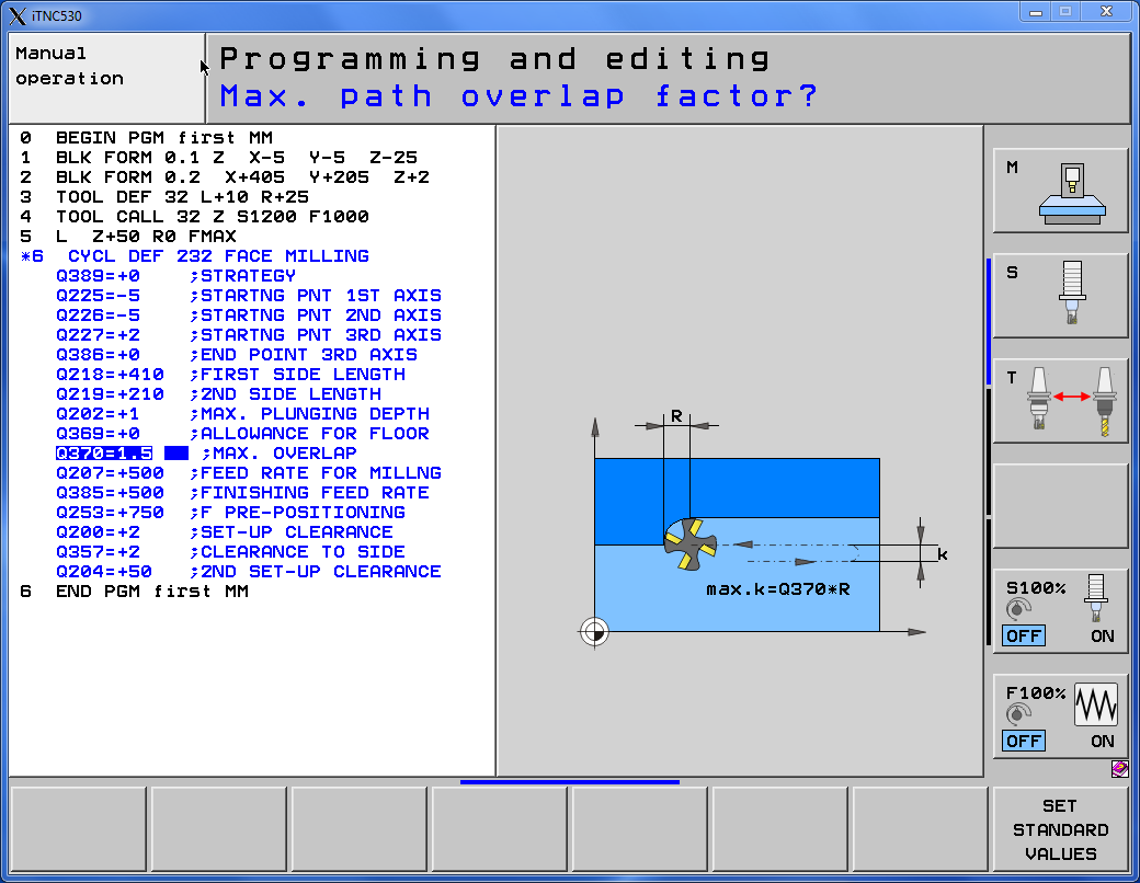
Enter 1.5 and press ENT.
Next option is the Feed rate for milling.
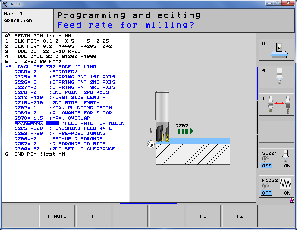
Enter 1000 and press ENT.
Next option is the Finishing feed rate. This is the feed rate for passes in the last Z-level. Passes closest to the floor.

Next option is the Feed rate for pre-positioning. This is the feed rate for tool approach for starting position and feed rate for movements between passes.
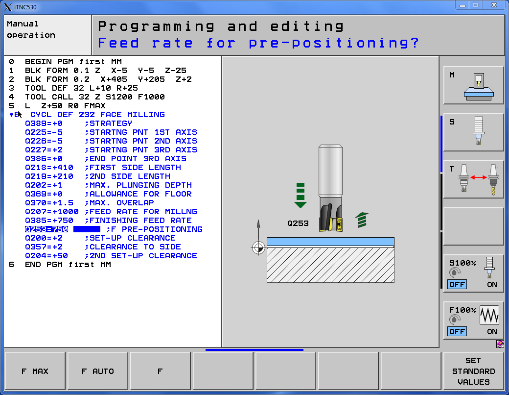
Enter 750 and press ENT.
Next option is the Set-up clearance. It is the safe distance from top of the stock. This parameter is useful with strategy 2. This is the distance for movements between passes on the same Z-level.
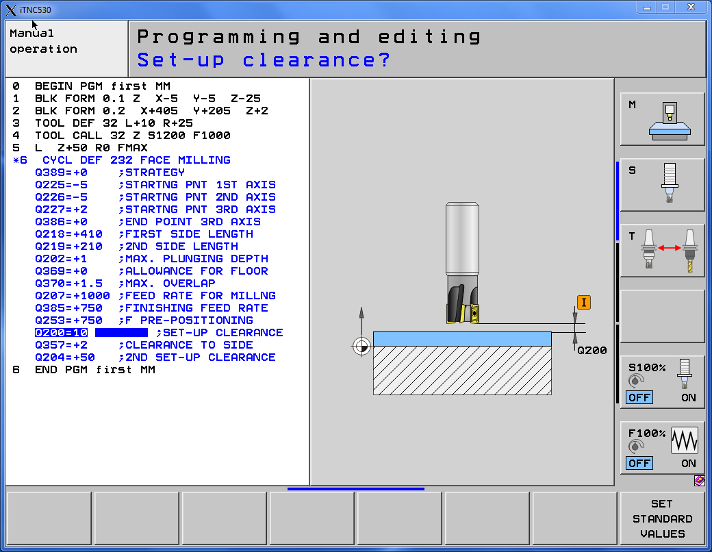
Enter 10 and press ENT.
Next option is the Clearance to side. It is the safe distance form stock sides.
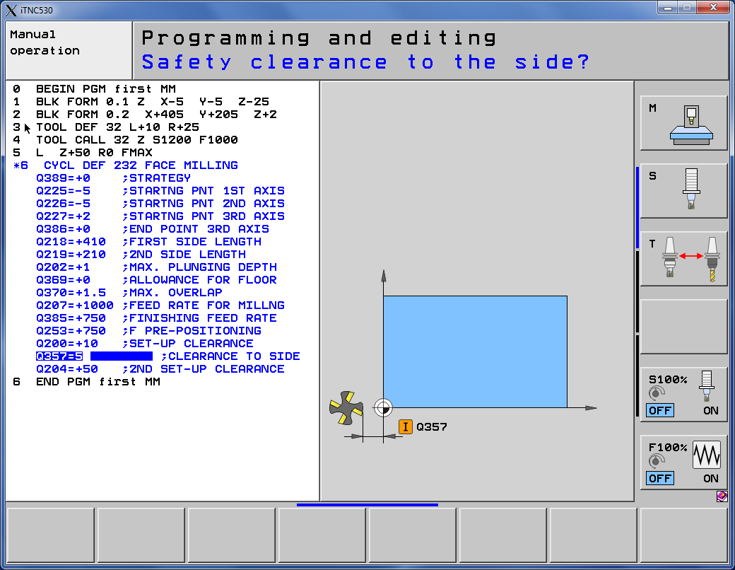
Enter 5 and press ENT.
Last option is the Second set-up clearance. This is the distance between stock and tooltip. Above this distance there is no possibility that there will be collision with the fixtures.
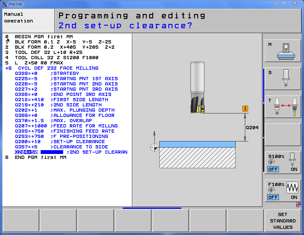
Enter 50 and press ENT.
We already have face milling cycle defined. In the next lesson we will call this cycle.
Watch the video below!
If you find my tutorials helpful, you can support CADCAMLessons:
https://ko-fi.com/cadcamlessons