If you find my tutorials helpful, you can support CADCAMLessons:
https://ko-fi.com/cadcamlessons
We’re practicing drawing – Lesson 9 – Alphacam Router Tutorial
YouTube: https://youtu.be/zKhxJL8O-5o
Now we draw the next part. Most of the functions we need to know are already known to draw this part.
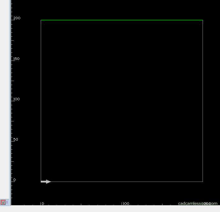
Let’s begin by drawing a square with a side of 200 mm. So we choose drawing a Rectangle. As the first corner let’s enter X0 Y0, as the second X200 Y200.
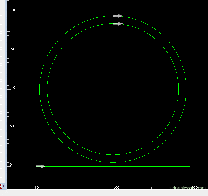
Then, draw two circles. One with a diameter of 170 mm and the other with a diameter of 190 mm. The center of both circles will be at X100, Y100.
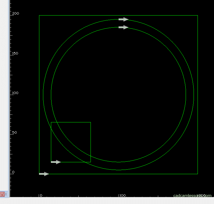
Now draw a square with a side of 50 mm. Select the drawing of the rectangle and enter X15, Y15 as the first corner and enter X65 Y65 as the second corner.
We could draw more squares. But we will make it easier and use the Array command from the Edit tab. This is something like a linear pattern.
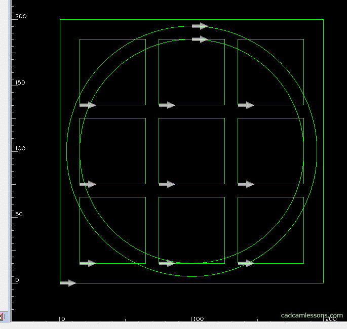
Pick a small square and accept the selection. As Number in X, enter 3, enter 60 as the Displacement in X. So we want to get three repetitions of the square in the X axis, each one separated by 60 mm from each other.
Similarly, we specify parameters in the Y axis. Three repetitions in the Y axis and each separated by 60 mm from each other.
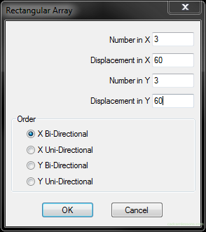
Click Ok. And now to bring this to the look we have on the example drawing, we need to delete unnecessary fragments of individual geometries.
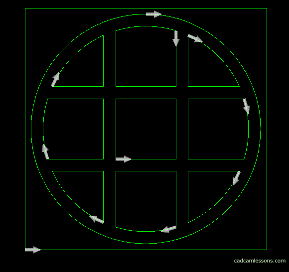
We will use the Trim function. Here, almost every geometry is a cutting geometry, i.e. a geometry to which we will be trimming, so just click on the button All (command line) and accept the selection. And now, carefully, click on those parts of the geometry that you want to remove.
If some geometry can not be cut, then we will simply delete it.
Now select the Delete option. I Select those geometries that remain after trimming.
Turn on the visibility of the geometry direction arrows, i.e. select from the View menu the Display Options | Ghost Tools.
There are quite a lot of these arrows here. Let’s join these geometries so that each separate geometry has only one arrow. To do this quickly and easily, select the Join command from the Edit tab. Click All on the command line and accept the selection. Alphacam will connect only those geometries that can connect, which are in contact with each other. It will not connect, for example, a square with a circle.
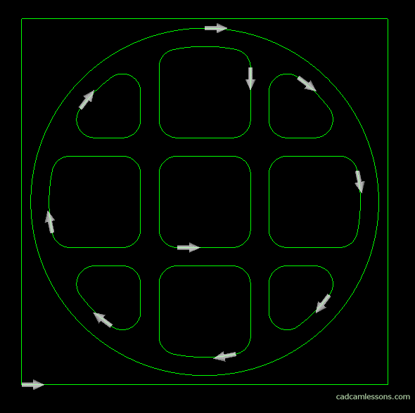
Ok, now I’ll show you how to quickly add fillets to all geometries. Select Fillet option (Edit tab), enter 10 as radius and select All. Click OK, click the All button to select all geometries, click on the large square to deselect it, because you do not want to fill in there. And ready.
As for a typical CAM system, Alphacam has quite a lot of functions that allow drawing and editing geometry. They are useful even when we use geometry from external CAD systems. That is why it is worth knowing at least the basic functions.
Save this part under the name p2-geometry-2d in the Alphacam Training folder.