
If you find my tutorials helpful, you can support CADCAMLessons:
https://ko-fi.com/cadcamlessons
G-code – Basic functions and parameters
YouTube: https://youtu.be/Vz72jsLHcbM
In the previous post I’ve provided some information about g-code. There will be some more information in this post.
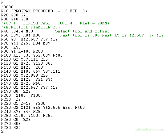
In block N10 we have a comment that will be visible on the machine’s desktop. We can include various useful information there. In blocks N20 and N30 we have the preparatory G functions.
G90 is absolute positioning, G40 is tool radius compensation off, G80 is the end of standard cycles, and G71 in this case means the use of metric units – millimeters.
Both of these blocks are written “rigidly”. This means that they will be generated in each machining program. It is a kind of security, reset settings, e.g. from the previous program.
Then, in block N40, we call the tool number 4 with the tool radius compensation value from block number 4. M03 is the right spindle speed.
In the N50 block we have the spindle speed setting at S999 rpm, H04 is the tool length compensation value, it will be read from field 4, from the tool table in the machine. M06 is a tool change command.
The next line, N60, we have in it a rapid move – G0, for certain XY co-ordinates.
Then in N70, we have G43 – enable tool length compensation, move G0 (because it was not canceled, if no other movement appeared, all the time the moves will be fast), we repeat the tool length offset value H04 and the functions responsible for coolant. M09 means just turning off the coolant. M08 is the coolant on.
In N80, we have a fast move to the Z5 coordinate.
In N90 we have the linear movement – G1, with the feedrate F200 mm/min, and the move in the Z axis to the Z-18 coordinate. The contour machining will be performed in the work movement. Lines N100 to N200 describe the shape of the tool path. In the meantime, the G2 coordinate appears, which means the circular movement of the tool in a clockwise direction (G3 is the circular movement of the tool counter-clockwise).
There is also a variable R, which is the size of the radius at which the tool moves.
In N260 we have the tool retraction with rapid G0 movement to the Z25 coordinate.
In N270, switching off the coolant.
In N280, M30 – end of the program and return to the beginning.
The ‘%‘ sign indicates the end of the data, the machining program information.
So that it was more or less what the machining programs look like and what it is all about, as in the future there will be references to the NC program.