
Heidenhain Programming and Editing
YouTube: https://youtu.be/ip6N1EC41N4
In this course, we will program the machining of a simple part, the drawing of which we created in the previous lesson about DraftSight.
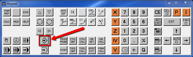
At the beginning, let’s enter the programming and editing mode.
Click by LMB (left mouse button) selected key in the picture below:
And now let’s click PGM MGT button.

PGM MGT button opens the file manager.
Use the arrows to go to the DEMO folder.
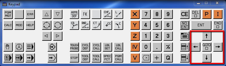
You can also use the mouse cursor to open the selected folder.

Let’ create new directory. Select NEW DIRECTORY softkey.
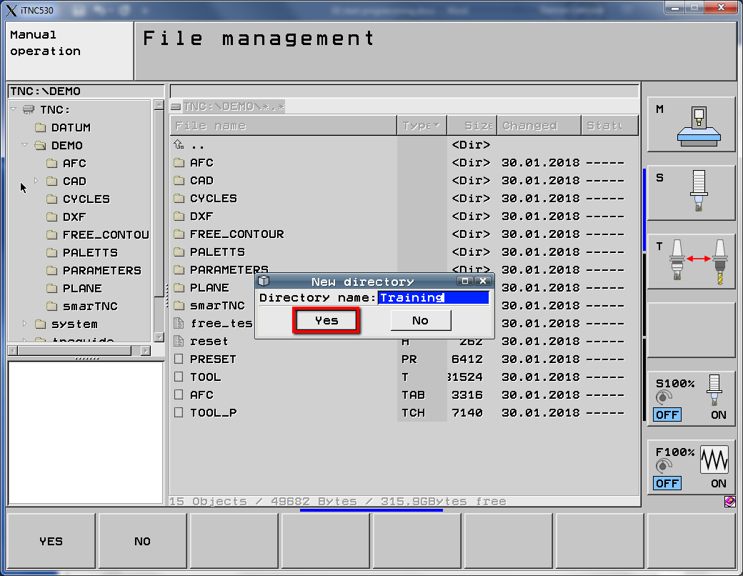
Enter the directory name – Training and click Yes button.
Let’s create NEW FILE.
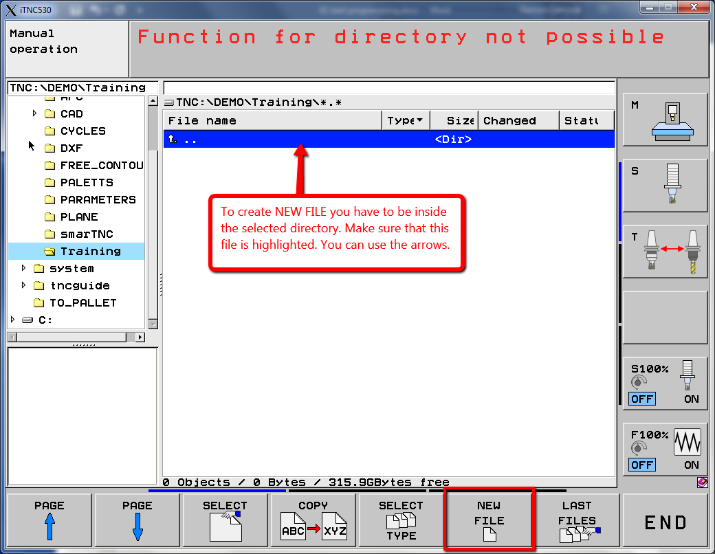
Press NEW FILE softkey.
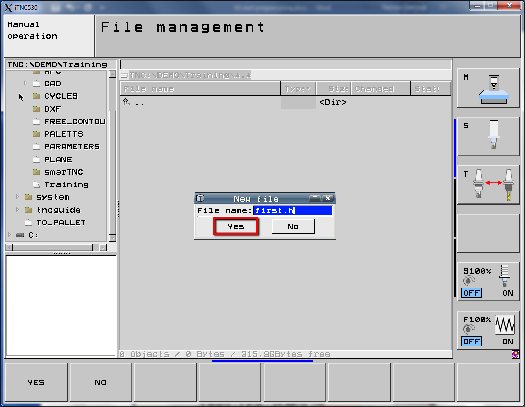
Enter the file name – first.h and click Yes button or YES softkey.
In the next step we have to select the file units.

I will select MM.
We can start programming.
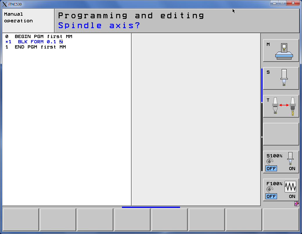
At the beginning we define the spindle rotation axis. By default, this is the Z axis (if a different one is selected, click the orange Z button).
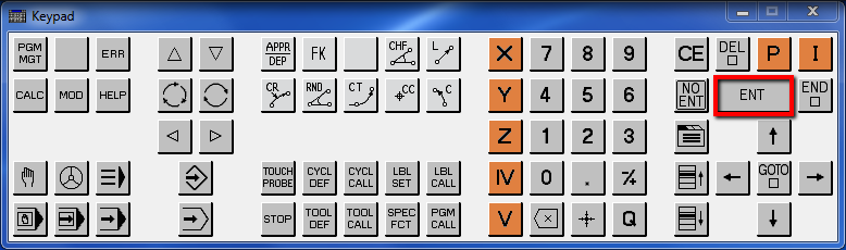
To accept, click the ENT button.
Now we have to specify the dimensions of the workpiece related to the beginning of the coordinate system.
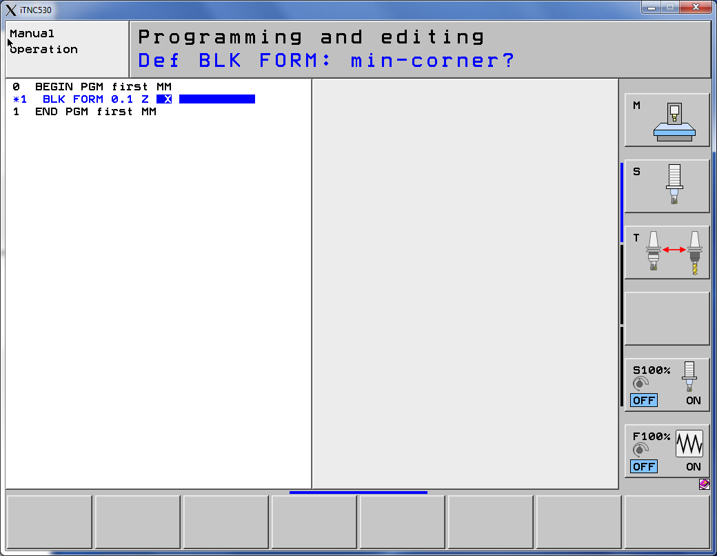
To make it easier to calculate coordinates from the drawing, the origin of the coordinate system will be in the lower left corner of the geometry, and the stock will be 5 mm larger on side.
BLK FORM in Heidenhain describes the stock size. We need to specify coordinates of min-corner and max corner. BLK FORM 0.1 is a coordinates for min-corner.
For X enter -5, press ENT, for Y enter -5, press ENT, for Z enter -25, press ENT.
BLK FORM 0.2 is a coordinates for max-corner.
For X enter 405, press ENT, for Y enter 205, press ENT, for Z enter 2, press ENT.
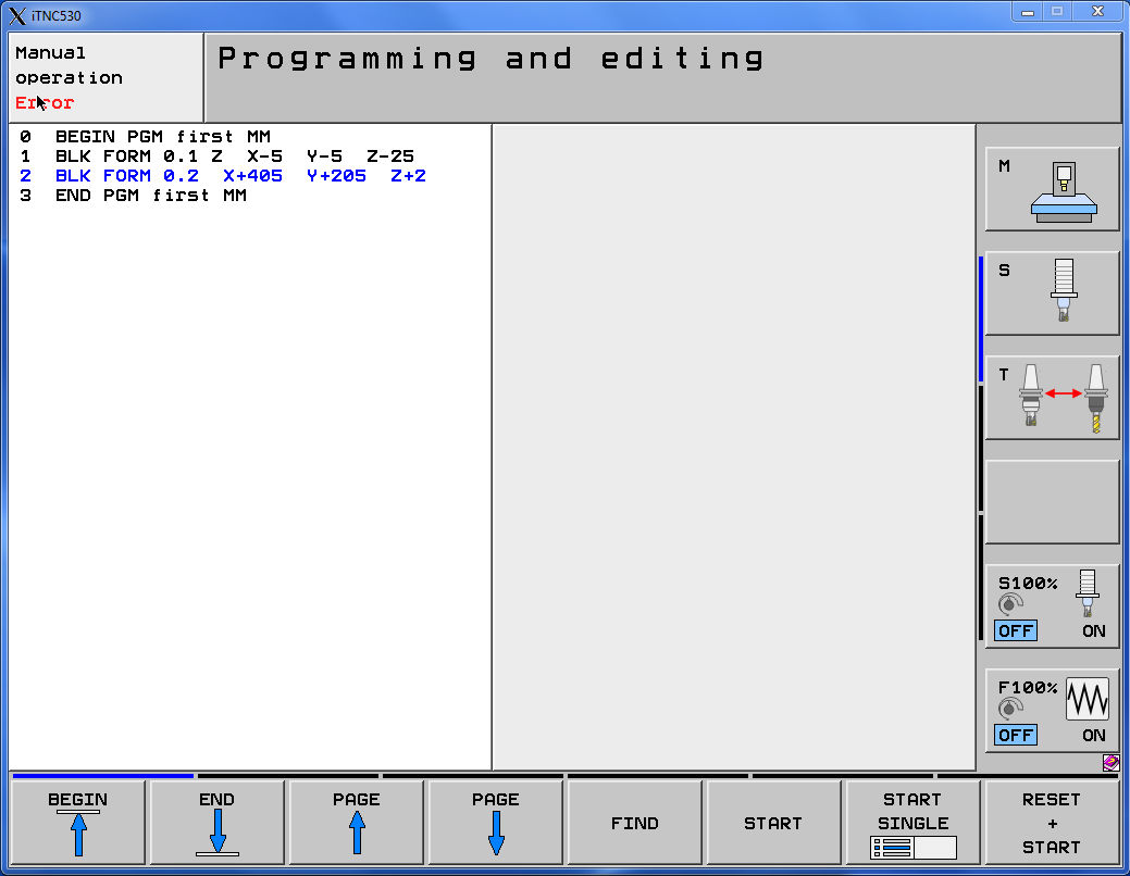
We have defined the stock size. Let’s create some code!
If you find my tutorials helpful, you can support CADCAMLessons:
https://ko-fi.com/cadcamlessons