
If you find my tutorials helpful, you can support CADCAMLessons:
https://ko-fi.com/cadcamlessons
Set Materials – Alphacam
YouTube: https://youtu.be/3A86nGoU7tY
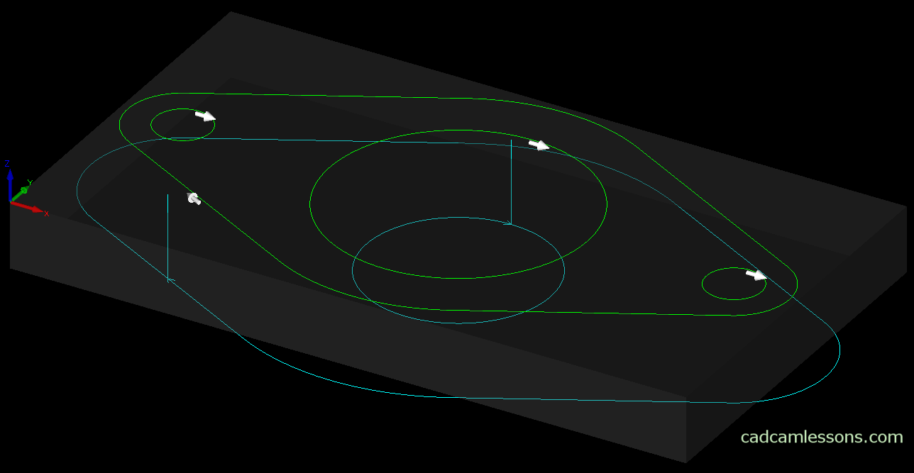
We already have the tool path in our project and we could already run a simulation. But we need material for solid simulation. The size of the XY of the stock is determined by a rectangle. We now have to indicate the rectangle as the material and specify the value in the Z axis.
Choose 3D | Set Material. In the command line will appear, MATERIAL: Pick Geometry or Solid. Select the rectangle and the following window will appear.

Specify Material Bottom: Z = -18. And the material will be set.
Top of material: Z – determines the top level of the stock.
Material bottom: Z – defines the bottom level of the stock.
Remember, the top of the material must be above the bottom of the material.
In the Material Type section, we specify the material type:
Main – this is the main part of the material. Let us assume that the most important in our project.
Additional – this is an additional material that we use in our machining, and this is a separate part. It is not connected to the main material. Sometimes there is a need to machine several parts, or several operations in one project. In Alphacam, we can only set one material as Main, but can add several Additional materials.
None – by choosing this option, we can undo the material setting process.
In the Select Texture section, you can specify the texture that the material will take during the simulation. We can upload our own textures to the C:\Alphacam\LICOMDAT\Textures.Alp folder.
The Set as Default option will set the currently selected texture as the default texture.
By selecting the Associate for auto-update option, Alphacam will consider previous machining and will not generate tool paths in places where previously machined material was. This applies in particular to cases where, after 2D machining, we use 3D machining. For example, we have machined something using 2D machining. By default, the 3D path will be generated wherever the initial material is, it will not take into account what we have done with the 2D strategy. Only by selecting this option and the appropriate option when generating 3D machining we will get that the 3D tool path will be generated only where the material after 2D machining remains. I will show it later on the example.