DraftSight Layers
YouTube: https://youtu.be/qj5gYA5OtOg
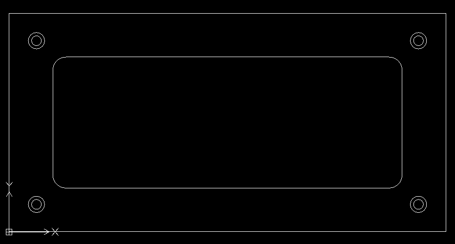
In the previous lesson we created a simple drawing. In this lesson, we will create a layer for geometries and separate layer for dimensions.
Open drawing from previous lesson.
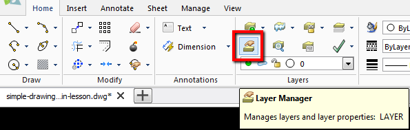
Select Layer Manager from the Home tab.
Window shown below will appear.
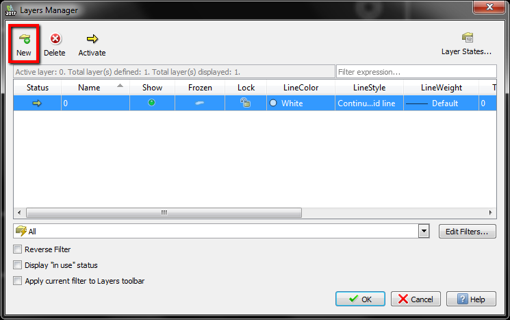
Select New button and fill data as shown below.
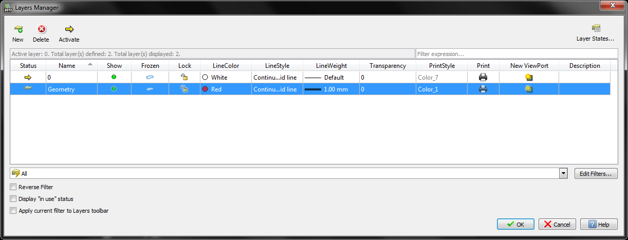
We’ve just added a new layer. We named it Geometry and set its color to Red. As a Line Style, we chose Continuous 1 mm thick line.
Add a new layer with parameters from picture below.
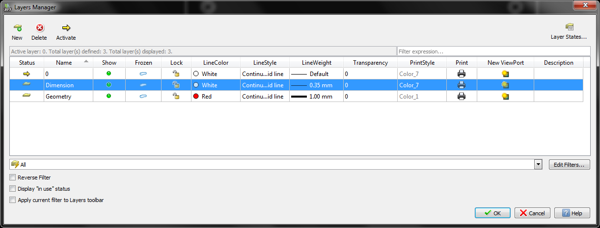
This is the layer named Dimension, White line color and 1 mm thick Continuous line.
Click OK button.
Select all geometries and expand Layers Manager menu.
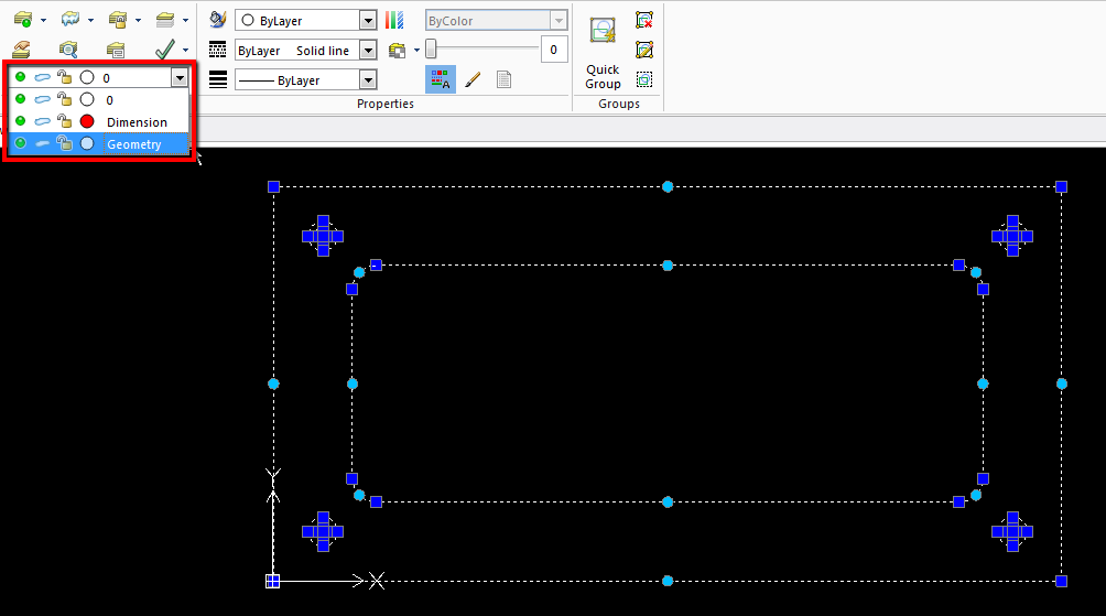
Select Geometry layer. All selected geometries will be moved to the Geometry layer and change to red.

We can also show the thickness of the line.
From the Manage tab select Options.

Window shown below will appear.
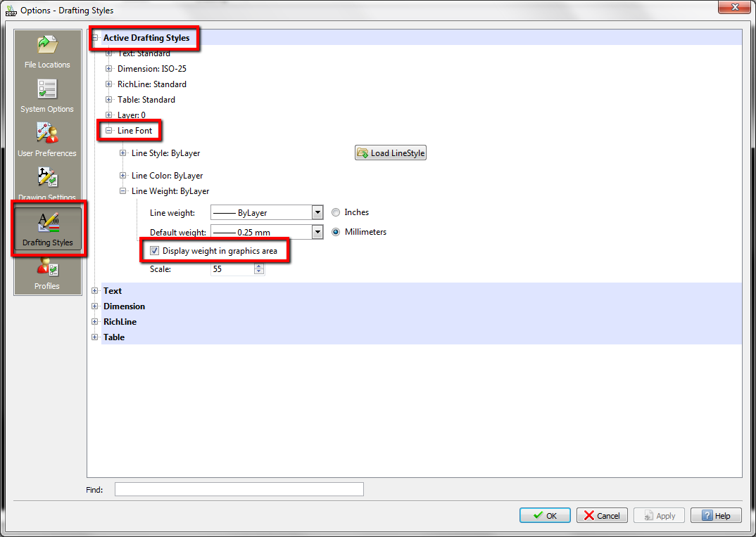
Select Drafting Styles, expand Activate Drafting Styles, next expand Line Font and next expand Line Weight and select Display weight in graphics area to show line thickness in the workspace.

The line looks too thick. We can edit this in Layer Manager but it may look good in print. Turn off showing line thickness to make the drawing more visible.
In this lesson, we’ve created two layers, but we can create more if you need it. It is very simple and can make the drawing more readable. Especially in assemblies.
In the next lesson, we dimension our drawing.
If you find my tutorials helpful, you can support CADCAMLessons:
https://ko-fi.com/cadcamlessons