Heidenhain Tool Definition
YouTube: https://youtu.be/fhETcOy_RbM
In this lesson we will define tool in Heidenhain.
It is very quick and easy.
There is two ways to define tool in Heidenhain – TOOL DEF command or edit Tool Table.
First, let’s check TOOL DEF command for tool definition in Heidenhain.
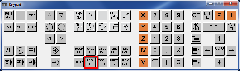
Press TOOL DEF key.
We have to define the tool number.

Press 32, press ENT. You can use different number.
Now, we have to define the tool length.
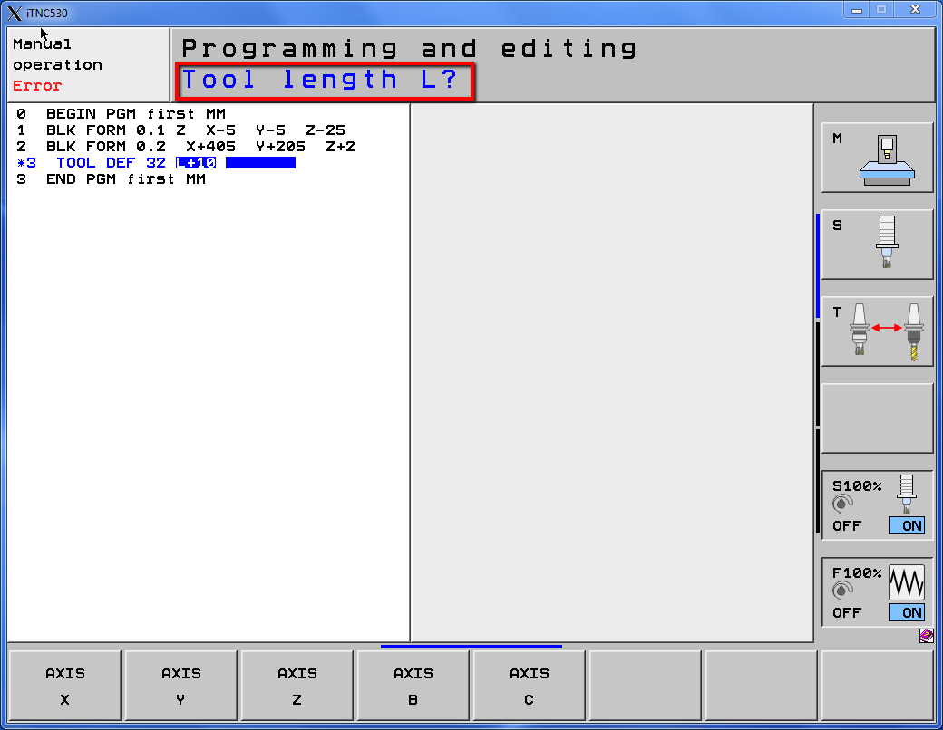
Enter 10 and press ENT.
Next, we have to define the tool radius.
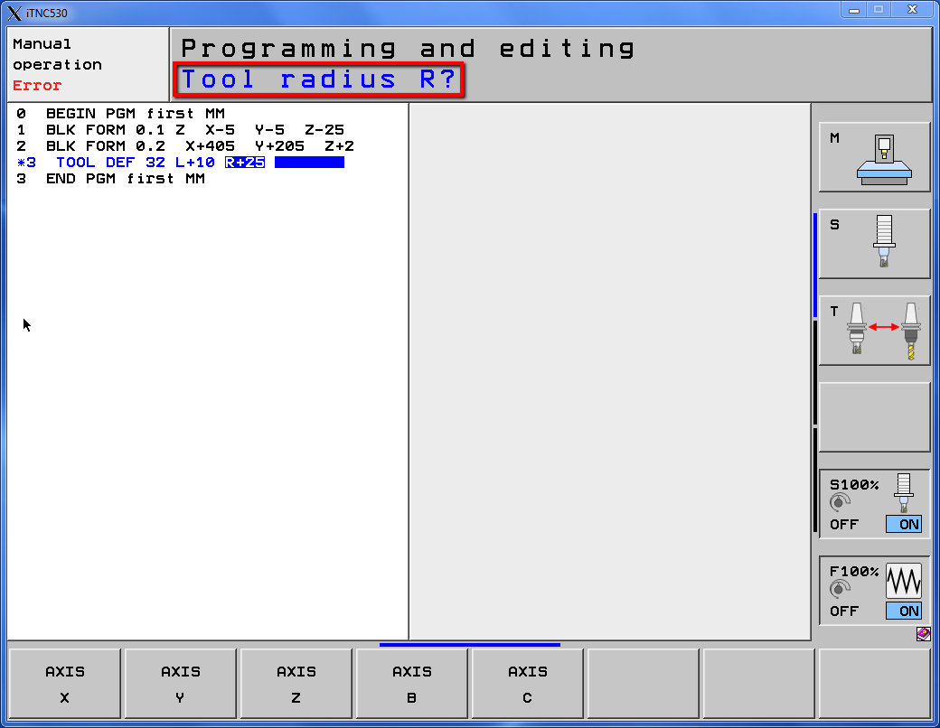
Enter 25 and press ENT.
The tool has been defined.
Let’s call our tool (tool has to be called before use).
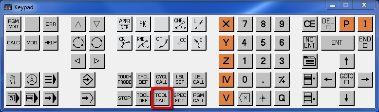
Press TOOL CALL button.
Enter the tool number.
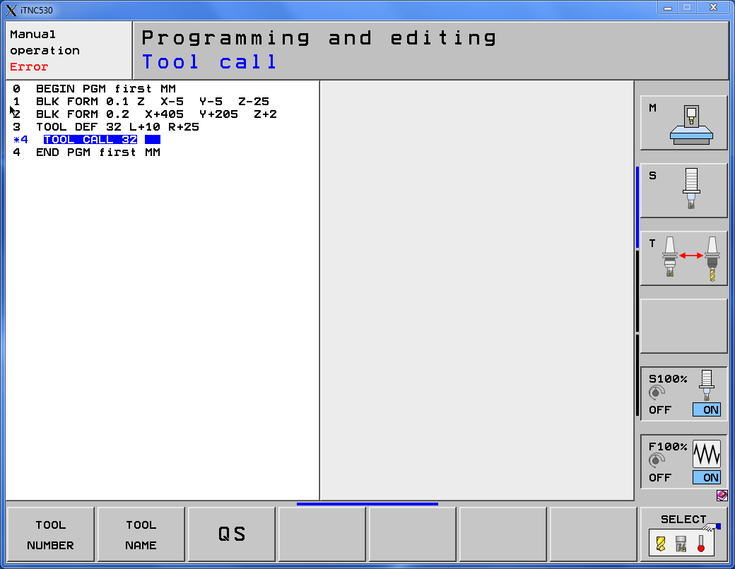
Enter 32 and press ENT.
Next, specify the spindle axis.

Accept Z axis by clicking ENT.
Set the spindle speed.
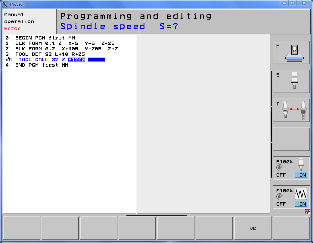
Enter 1200 and press ENT.
Set the feed rate value.
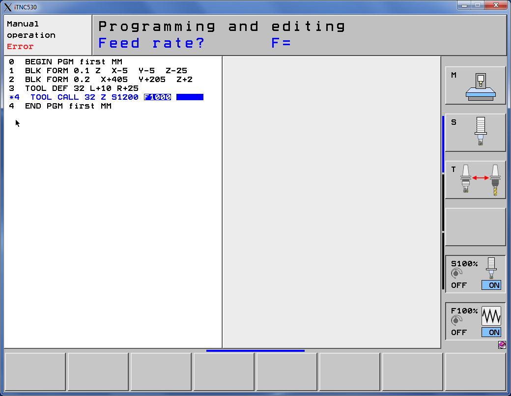
Enter 1000 and press ENT.
Skip setting tool length oversize.
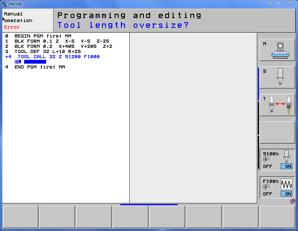
Just press ENT.
Also skip setting tool radius oversize.
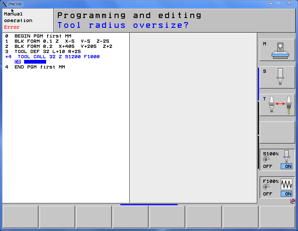
Again, just press ENT. And repeat this for tool radius oversize 2.
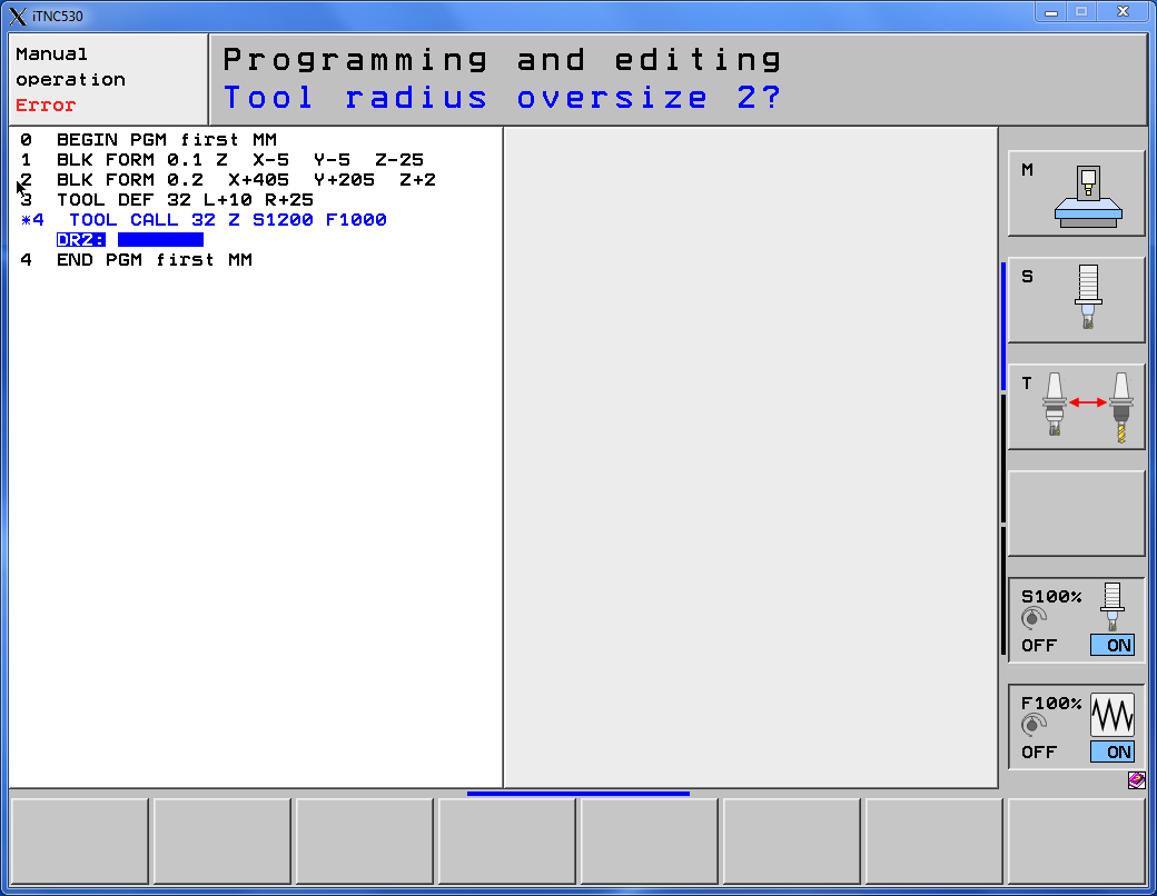
Press ENT.
We already have a tool called.
Let’s prepare the first move.
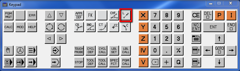
Press L (line) button.
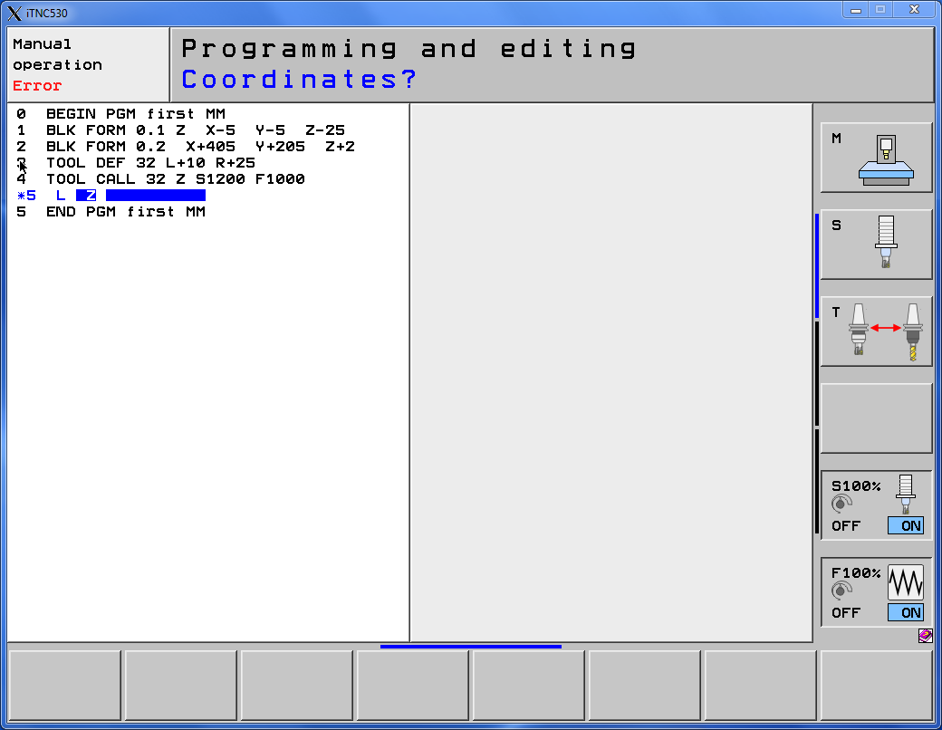
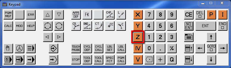
First, change axis to Z by clicking orange Z button.
Enter 50 and press ENT.
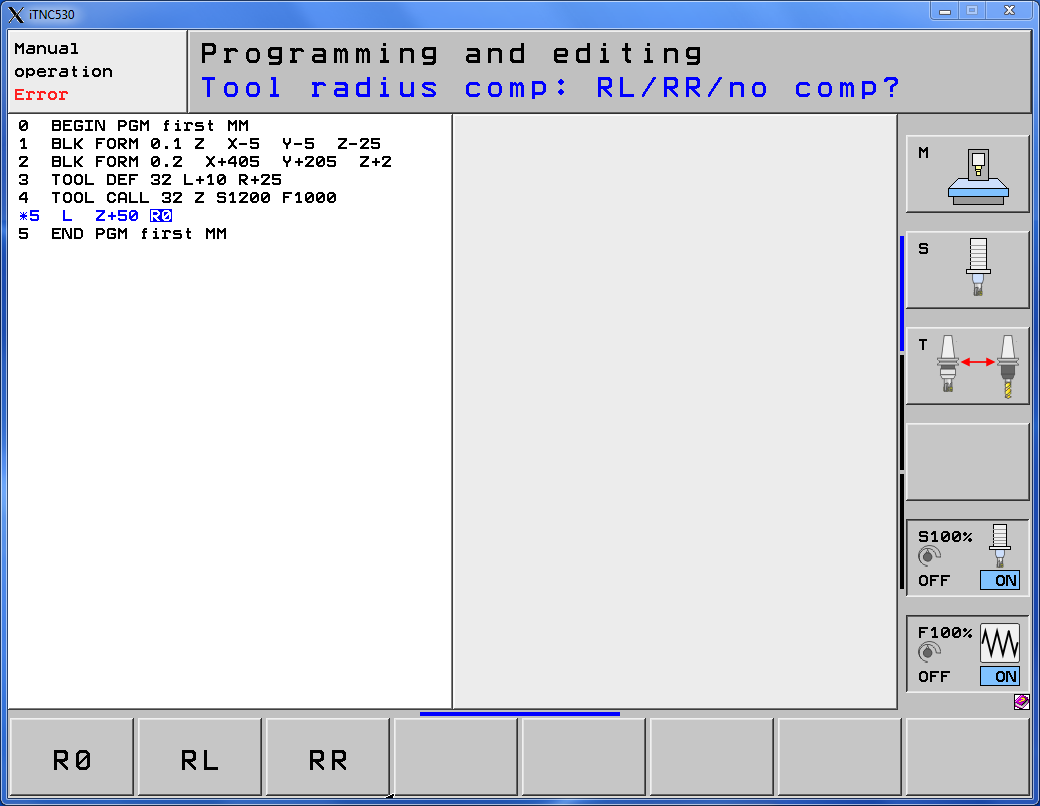
Select R0 option – no compensation, and press ENT.
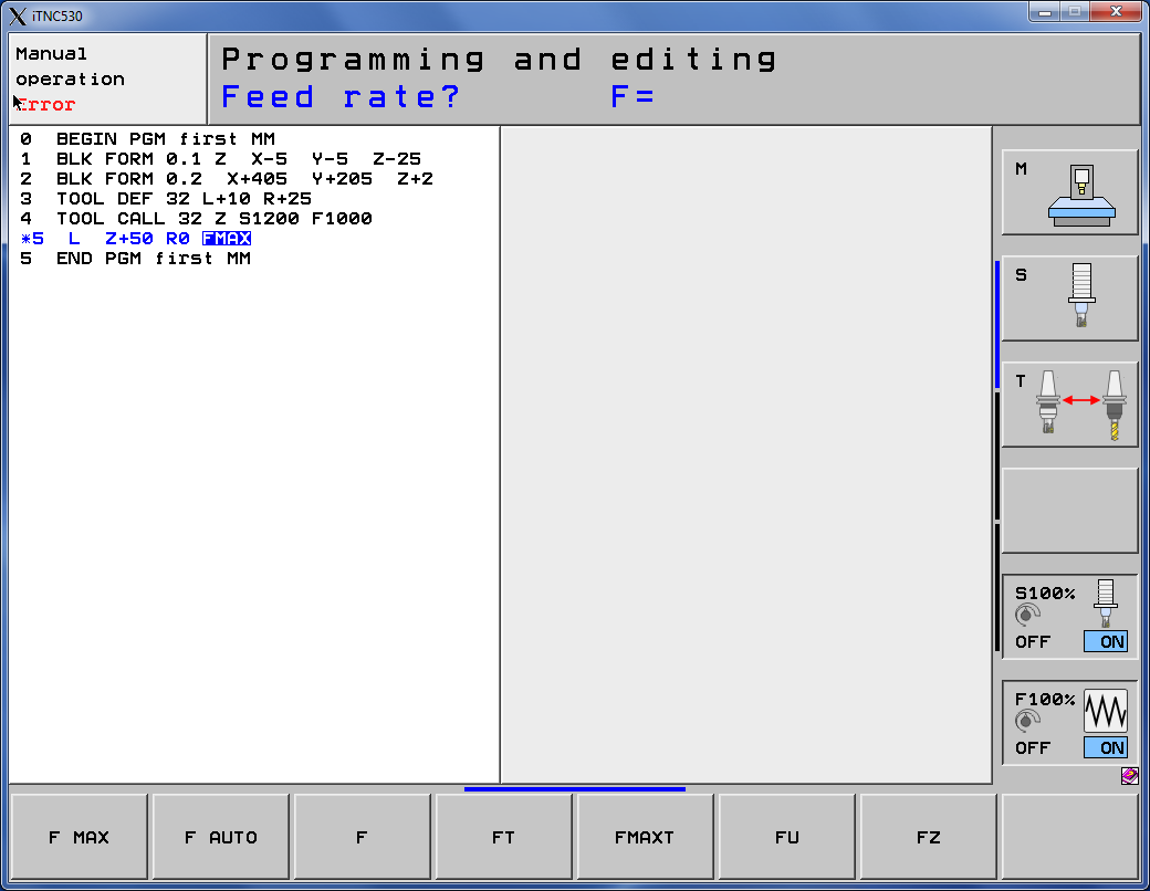
Select FMAX by clicking F MAX softkey.
And press END button to finish line.


Heidenhain Tool Definition with edit tool table we will check later.
In the next lesson we will prepare face milling operation using Heidenhain cycle.
If you find my tutorials helpful, you can support CADCAMLessons:
https://ko-fi.com/cadcamlessons