If you find my tutorials helpful, you can support CADCAMLessons:
https://ko-fi.com/cadcamlessons
Define Tool – Lesson 11 – Alphacam Router Tutorial
We need a tool to start machining. Alphacam has a library of several tools that are installed by default. But you will not use them in your everyday work.
Therefore, we will define our own tool with specific parameters.
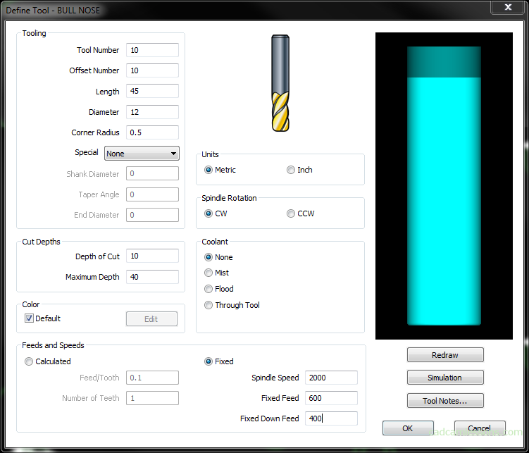
From the Machine tab, select the Define Tool. First, we define a Bull Nose type. E.g. 12 R0.5.
In the window with a choice of tool type, select BUUL NOSE.

Enter 10 for the Tool number and Offset Number. These are the values that will be generated in the part program. Tool number 10 will cause the tool to be called from slot 10 in the machine tool magazine (or the one that is assigned to that slot). And if we define machining with tool offset, the tool offset value will be read from the tool offset value field. The most common rule is that the value of the tool’s offset number is the same as the tool’s number. And that’s what we stick to in this course.
Of course, to apply tool offset, we must select the appropriate option in the machining strategy.
In the Length field, enter 45. This is the tool length, excluding the tool holder.
Enter 12 in the Diameter field and 0.5 in the Corner Radius field.
In the Units section, we specify whether we use metric or imperial units.
In the Spindle Rotation section, select the direction of the spindle rotation, select CW, i.e. clockwise rotation.
In the Coolant section we specify the type of tool cooling.
There are two parameters in the Cut Depths section. The Depth of Cut, it is the effective length of the flutes, enter 10. Here, so maximum depth that tool can mill in one pass.
And the Maximum Depth parameter is the effective length of the blades plus the ‘neck’. Enter 40 here and it means that the tool can go up to 40 mm in material. But in one pass it can mill a maximum of 10 mm. So we can make, for example, 4 passes of 10 mm, and we can’t do it anymore because we will machine the material with the tool shaft.
In the same way, we cannot machine more than 10 mm in one pass and if we want to machine deeper in one pass, we will also cut it with a shank or break the tool.
The next section is Feeds and Speeds. Here we set the parameters with which the tool will work.
Select Fixed and enter 2000 as Spindle Speed, Fixed Feed 600, Fixed Down Feed 400. Spindle speed is given in revolutions per minute, and feed in mm/min.
We will add a simple tool holder to this tool. Click Simulation button. In the Holder Simulation section select Simple and in the Tool Holder section enter 60 as the Length and 40 as the Diameter. This will give us a simple model of the holder in the form of a cylinder.
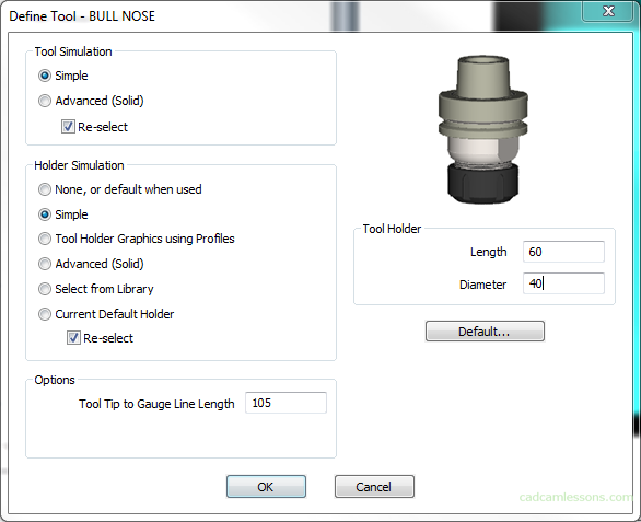
However, it is worth using it, because if we accidentally specify the bigger than possible milling depth, it will show us the collision during simulation and we will be able to change it while programming the machining.
To save the tool, click OK. The default tool location will open. Let’s create a new folder called Alphacam Training. Let’s save the tool under the name Flat12R05.
YouTube: https://youtu.be/OtBGGGkXweQ