If you find my tutorials helpful, you can support CADCAMLessons:
https://ko-fi.com/cadcamlessons
Rough or Finish – Lesson 12 – Alphacam Router Tutorial
Machining strategies in Alphacam are located in the Machine tab. To be able to choose a machining strategy, we must first select a tool.
From the Machine tab, select the Select Tool option. The Alphacam tool table appears. Initially, it opens with a list of tools that install with the Alphacam installation. But here we also have a list of folders and choose the Alphacam Training folder in which we saved the tool.
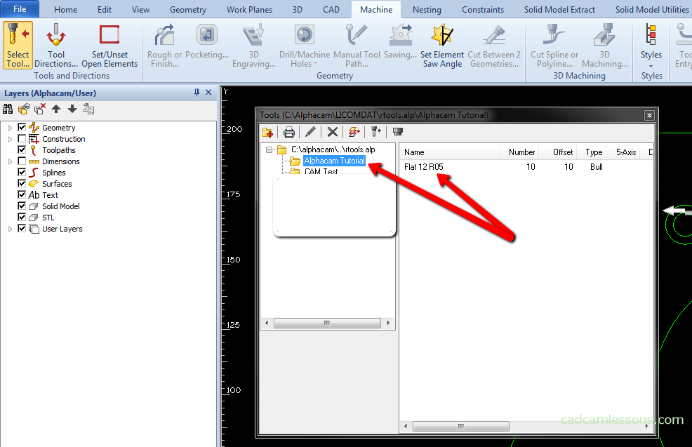
Let’s choose the tool Flat12R05. To select a tool, double-click the left mouse button and then left-click again to accept the selection.
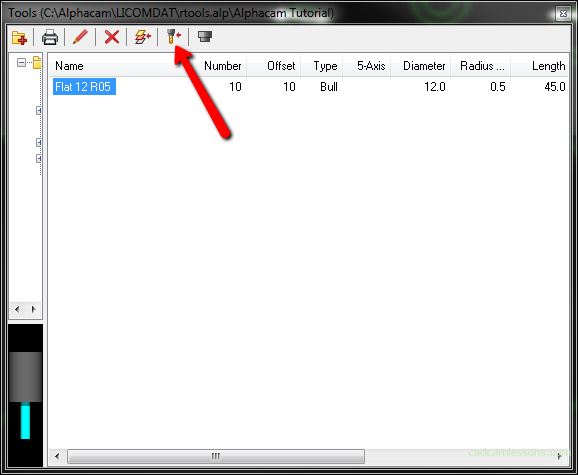
You can also select a tool and click the Select Tool button. And then accept the tool selection by clicking the left mouse button in the work area.
Now we can choose a machining strategy. We will start with machining contours. Contour machining it is a generating a tool path along the indicated contour.
From the Machine tab, select Rough or Finish.
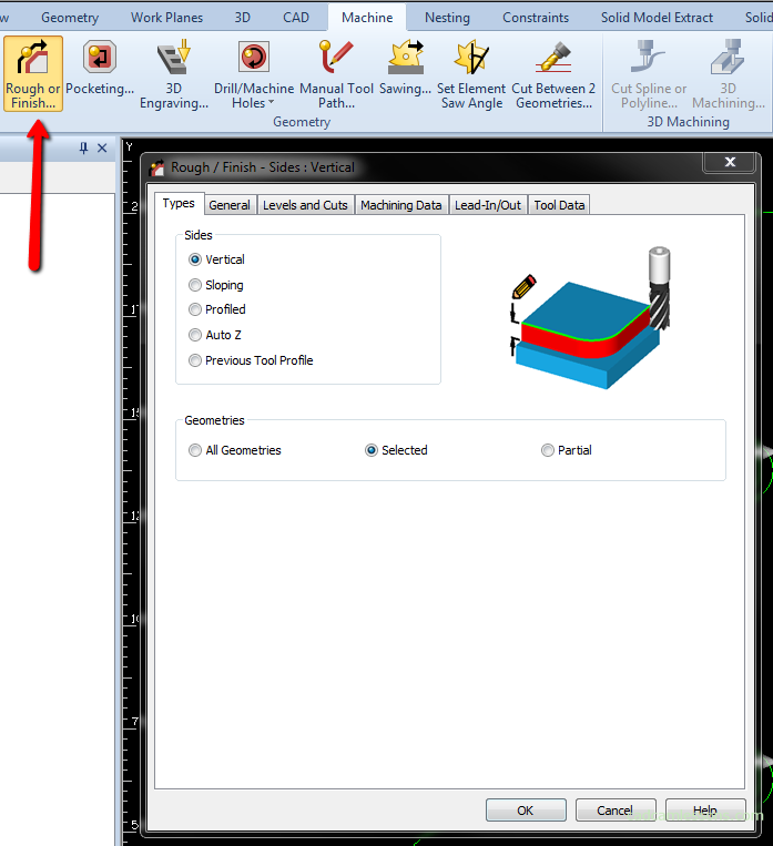
In the first tab, in the Types tab, we specify the type of contour processing. The Vertical option is responsible for standard contouring and we will focus on it. In the Geometries section, we choose how we want to indicate the geometries to be machined. By selecting the All Geometries option, all geometries from the drawing will be selected for machining. By selecting the Selected option, we manually indicate the geometries that we want to machine in this operation. And by choosing the Partial option, we can prepare the machining of a fragment of geometry. So if we have our outer contour, and we want to prepare machining of only one side, we can use this option.
Choose Selected here and go to the General tab.
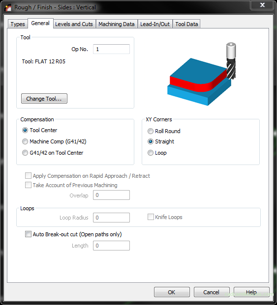
In the Tool section we have information about the tool that will be used for this operation and here we can also change the tool by clicking the Change Tool button and selecting another from the tool table.
In the Compensation section, we specify whether we prepare machining with or without tool compensation. If we want to prepare machining without tool compensation, we simply choose the option Tool Center, and if we want to prepare machining with tool compensation, select the Machine Comp (G41/G42).
Let’s choose the option without compensation.
The XY Corners section is responsible for the appearance of the tool path on the outer corners. This will show later on an example. Here, select Straight.
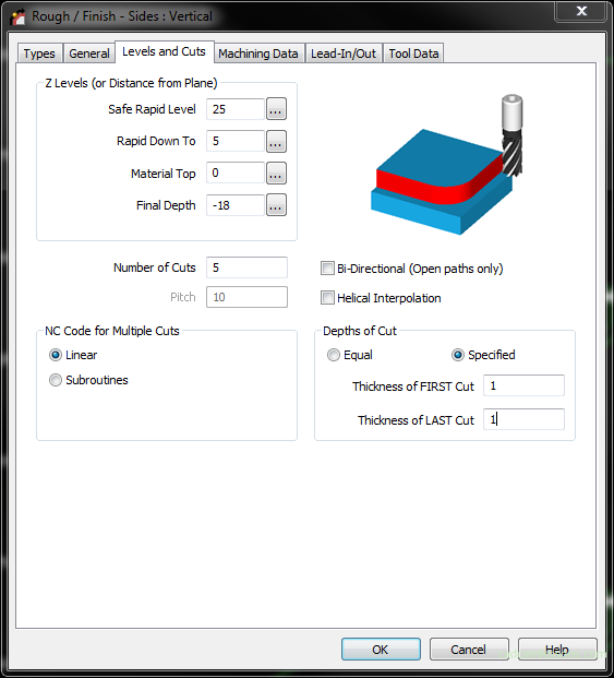
Let’s move to the Levels and Cuts tab. In the Z Levels section we specify the machining levels. Safe Rapid Level means the level of safe height at which the tool can move freely in a rapid move, e.g. between operations.
The Rapid Down To means the level at which the working feed will be activated. The tools at the Safe Height level are set at the XY coordinates of the tool in and move quickly in the Z axis to the height of the Rapid Down To and will start working feed at this point.
The Material Top simply determines the top level of the material, and the Final Depth determines the milling depth.
The Number of Cuts parameter defines the number of passes that will be generated between the material top and the final depth.
The Depths of Cuts can be Equal or Specified, we can specify the depth of the first pass and the depth of the last pass.
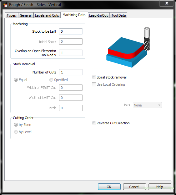
In the Machining Data tab in the Stock to be Left field we can leave the allowance on the contour for finishing machining.
In the Lead-In/Out tab, you can specify how the tool enters the material and how the tool leaves the material. We will return to this tab in a moment.
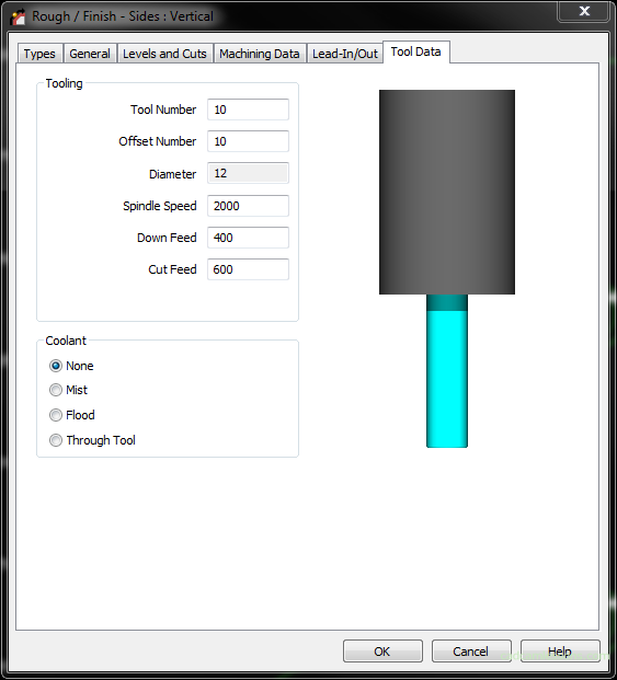
In the Tool Data tab we can change selected tool parameters. Changing these parameters will only apply to this particular operation. It will not affect the global definition of the tool.
Click OK and select the outer contour.
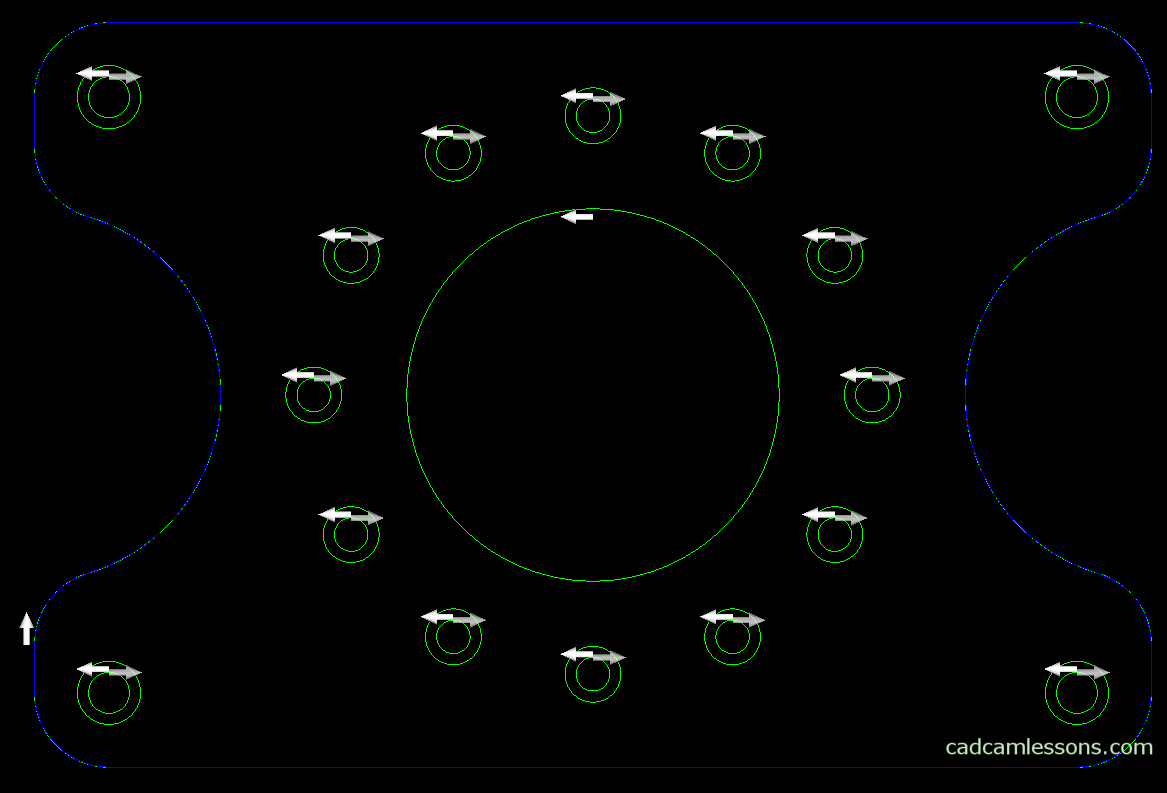
And let’s accept the right mouse button.
Let’s switch to the Iso view.
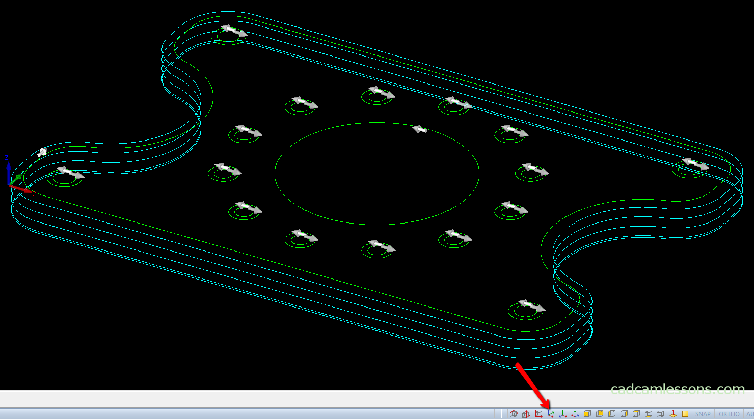
You can see that we have the contour machining in five passes. Of which the first and last are 1 mm deep.
Let’s change the place and the way the tool enters the material.
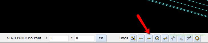
To change the entry point of the tool into the material from the Edit tab, select the Start Pt option.

And then indicate the center of the long side, e.g. with the MID-point of snap.
The operation name changed to blue, an asterisk appeared next to the operation name.
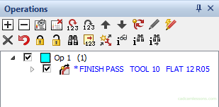
The tool path needs updating.
This means that you need to update the tool path after the changes are made. Right-click the operation name and select Update.
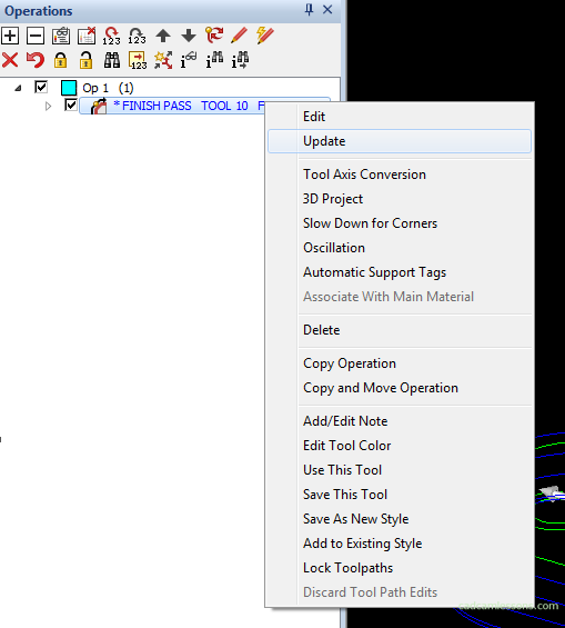
Let’s change the way the tool enters the material. Right click on the operation and select Edit.
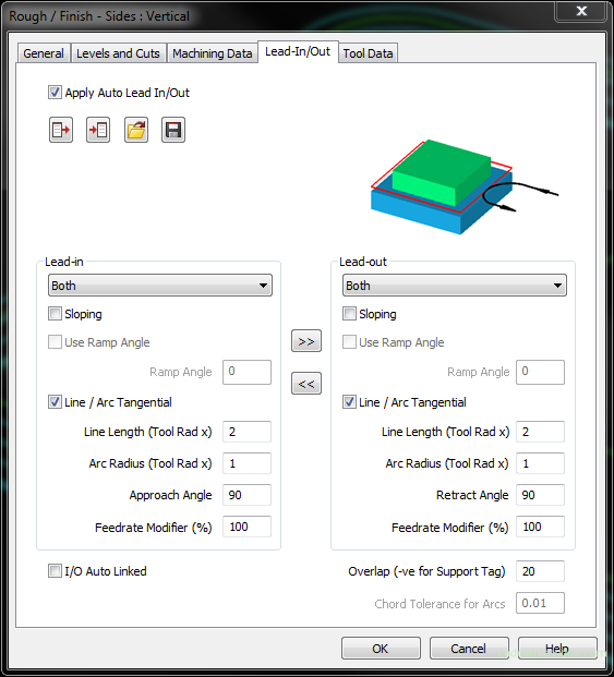
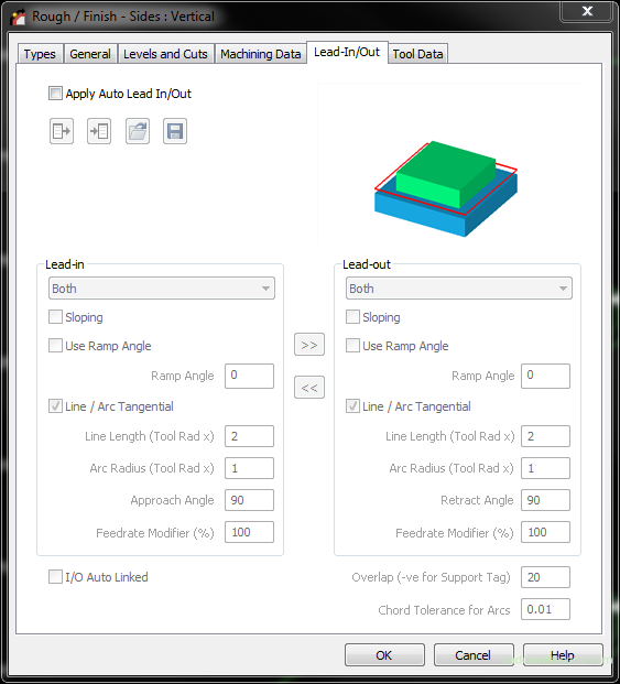
Go to the Lead-In/Out tab. And to change the way the tool enters the material, select the Apply Auto Lead In/Out option.
We can use the input of the tool by line, arc or as a combination of line and arc. Choose Both to get the entrance, which will consist of a line and an arc.
If we want the line and arc to be tangent, select this option.
The Line Length option allows you to specify the length of the input line. The value of this parameter is the tool radius multiplier. So typing 2 here, we get a line length of 12 mm.
The Arc Radius is a parameter with which we determine the radius of the arc of entry and as in the case of the length of the line it is a multiplier of the tool radius. So the radius of the entrance arc will be 6 mm.
The Approach Angle is the arc angle and the Feedrate Modifier parameter allows you to modify the feed value for the input.
We can immediately add parameters for the tool output. To use the same parameters as for the input, just click >> button.
We have another important parameter here – Overlap. With this parameter, we can make the tool exit point from the material not coincide with the entry point.
The exit point will be moved past the entry point by the entered value.
Click OK and see how the tool path changes.
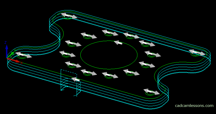
Input and output of the tool look good. The tool will start the entry on the line, and then gently enter the material on the arc. In addition, the tool exit point from the material is shifted 20 mm relative to the tool entry point into the material.
Now let’s add pocket machining.
YouTube: https://youtu.be/5T__V149VP0