Heidenhain Contour Machining
YouTube: https://youtu.be/kme7vvdhZ9k
Contour machining in Heidenhain.
In this lesson, we will prepare the contour machining.
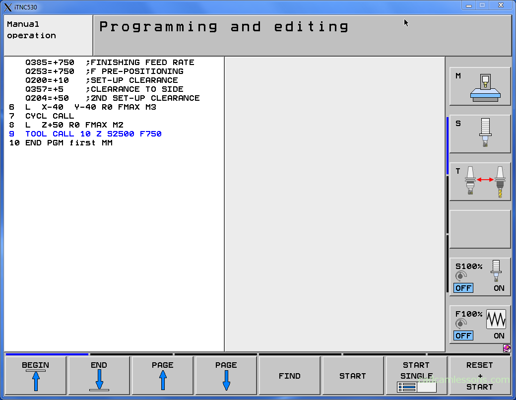
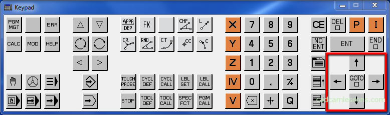
First, we have to change tool. Press the TOOL CALL button.
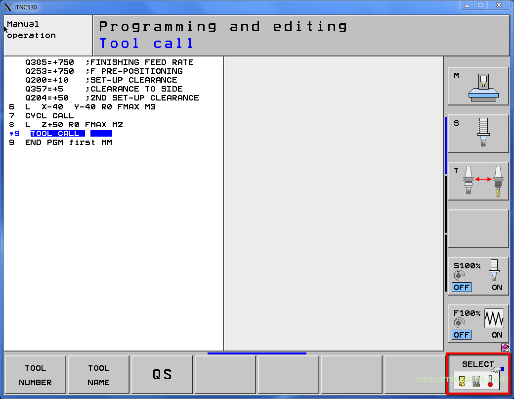
And next press the SELECT softkey.
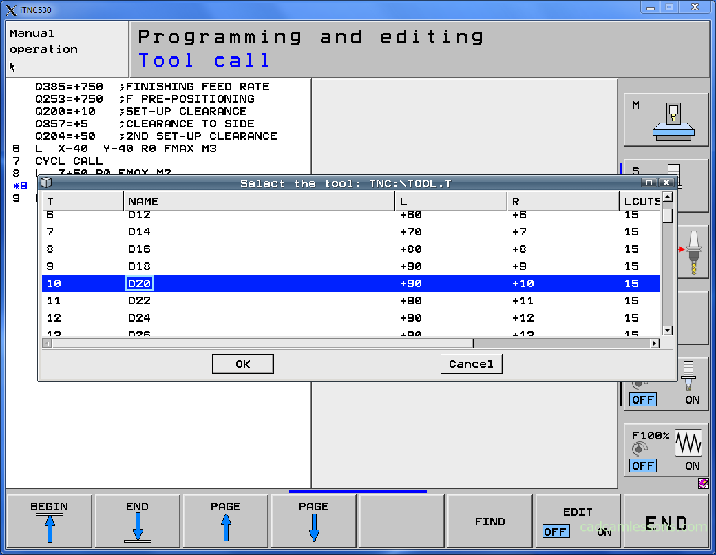
Select T10 D20 tool and press OK.
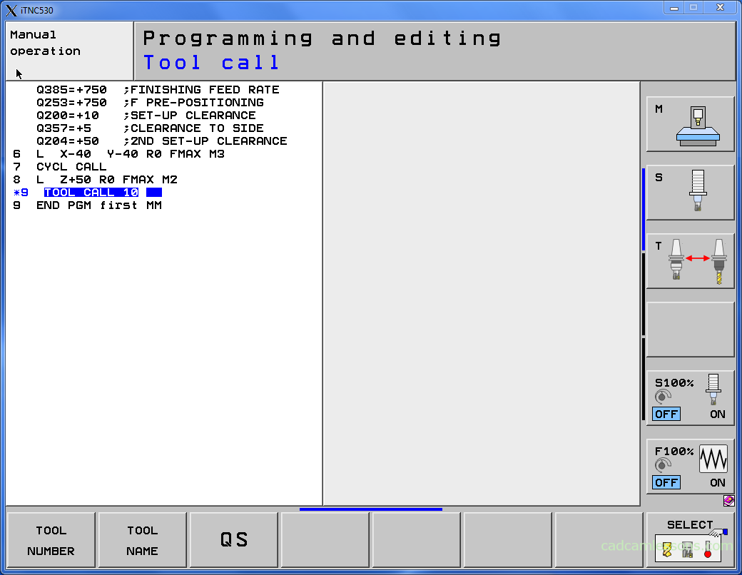
Press ENT button.
As spindle axis set Z.
Spindle speed S = 2500.
Feed rate F = 750.
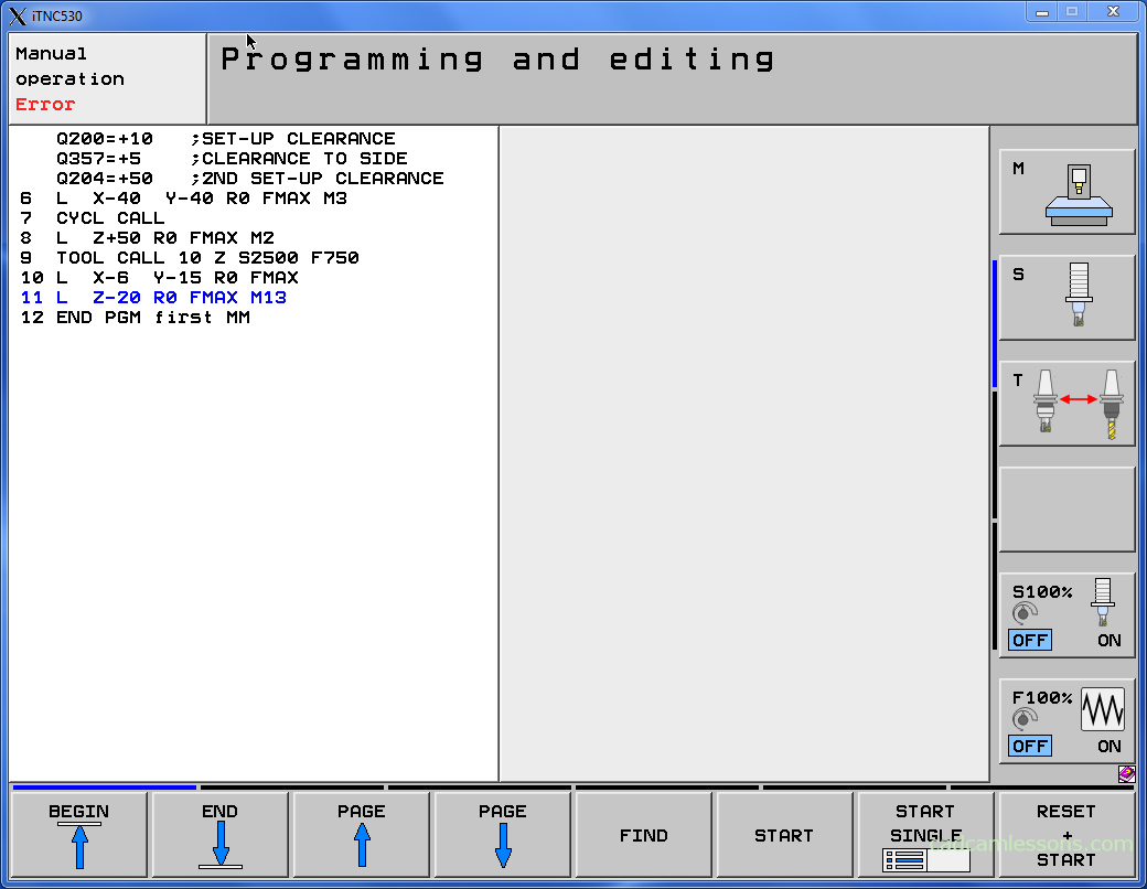
Now we can prepare contour machining. We have to start outside the contour and we must consider the tool radius.
Press the L button and enter X-6 Y-15 R0 FMAX (remember, to put Y value you have to press the right-arrow, near to GOTO button). R0 means we don’t use tool cutter compensation.

Again press L button and enter Z-20 FMAX M13.
M13 means right spindle rotation direction ON and coolant ON.
FMAX in Z axis is a little bit dangerous. We have to sure that tool is outside the material and there no fixture.
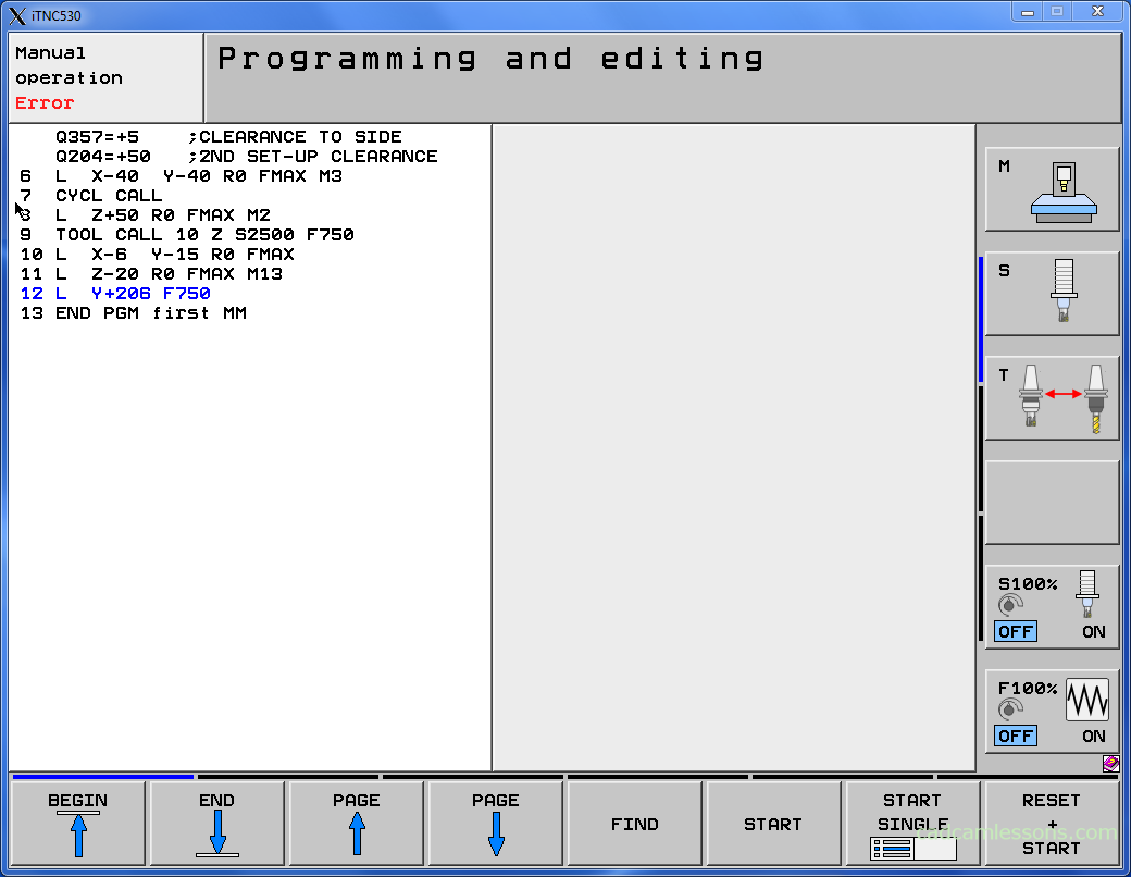
Press L button again and enter Y+206 F750.
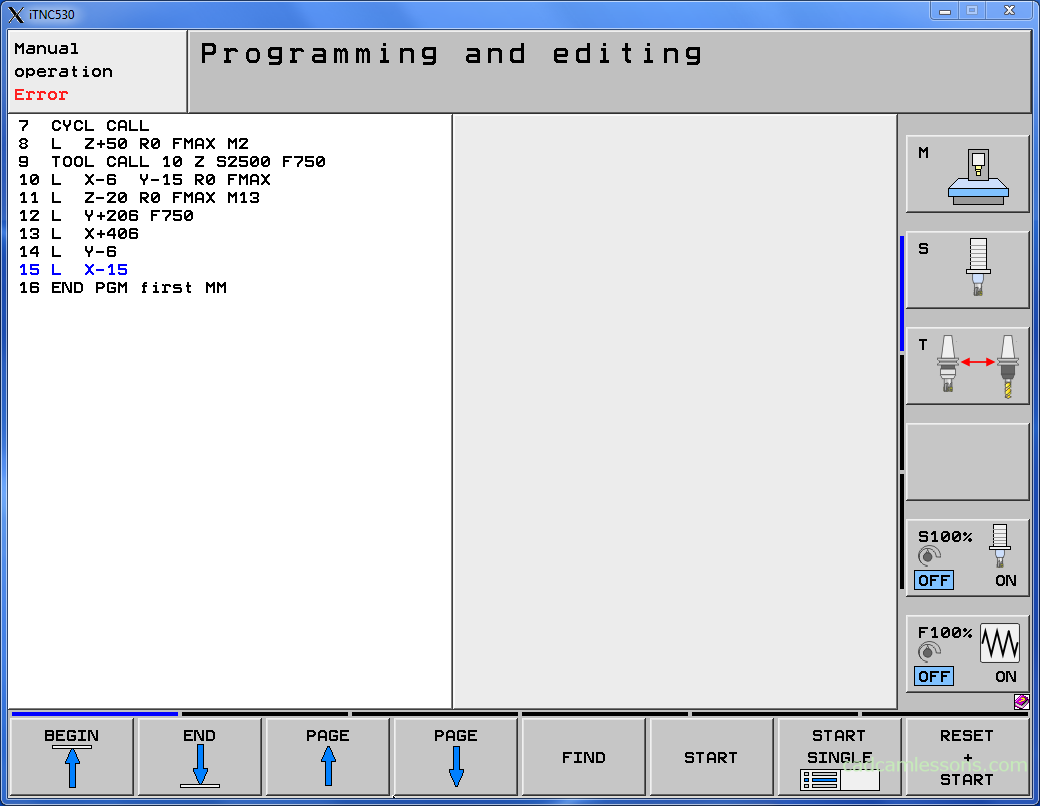
Press L button and enter X406.

Press L button and enter Y-6.

Press L button and enter X-15.
Now we have to prepare tool retract to Z+50. Press L button and enter Z+50 R0 FMAX M2.
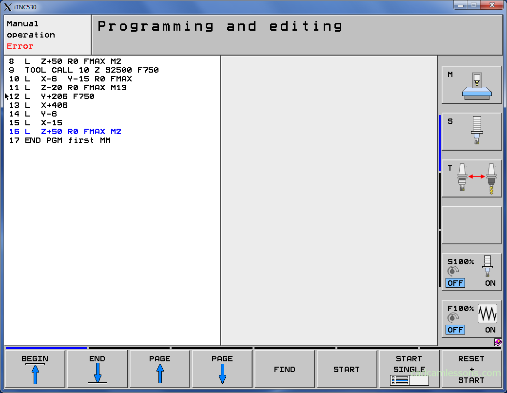
And let’s run the simulation. Probably you will see only simulation of face milling operation. Why?
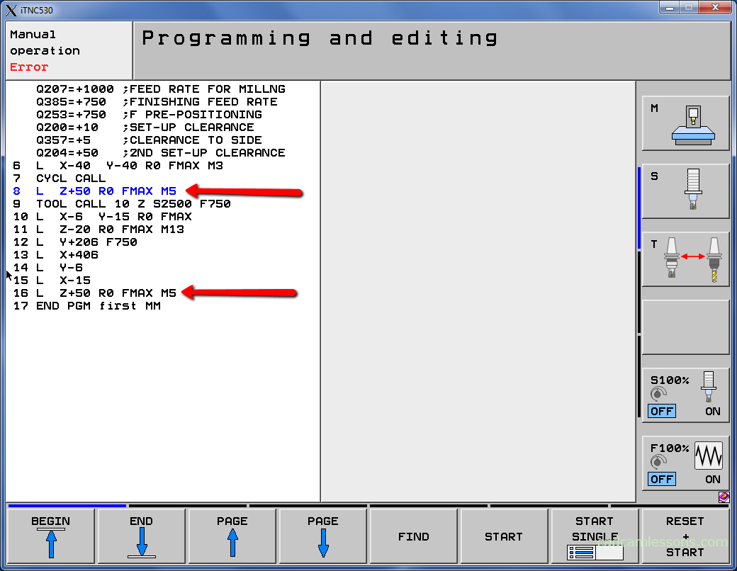
Because we used the M2 function too early in the code. We have to change M2 for M5.
M2 means Stop program run (Spindle STOP, Coolant OFF, Go to block 1).
M5 means Spindle STOP.
Using arrows:
Edit program to get:
Now we can run the simulation and we should get:
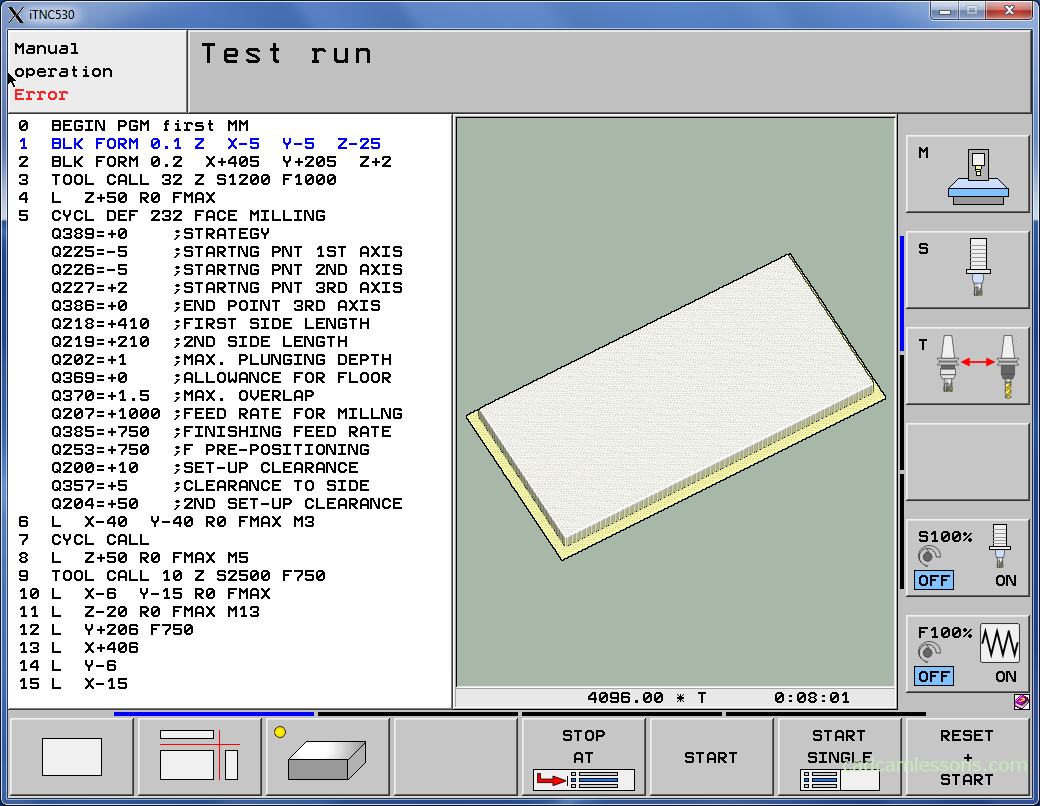
You have to noticed that the entire contour is machined in one pass. There is a big risk that the tool will be damaged. It would be better to divide the machining into several passes. Does this mean that we must describe the contour for each pass? Fortunately not. We will discuss this in the next lesson.
If you find my tutorials helpful, you can support CADCAMLessons:
https://ko-fi.com/cadcamlessons