Fusion 360 CAM Tutorial
Definition of the origin of the coordinate system in the CAM system.
YouTube: https://youtu.be/2n684TlctVg
Autodesk Fusion 360 is a CAD / CAM / CAE class system, but for our purposes we will mainly use the CAM module.
Knowing one CAM system, we can quickly master new systems. Sometimes knowing one system disturb with getting to know each other, but only at the beginning. As we know one CAM system, getting to know the next is mainly getting to know the user interface.
The rules are similar everywhere. Definition of the coordinate system, selection of geometry to be machined, tool selection, parameters selection, calculation of tool paths, simulation and generation of machining programs. This is what it looks like in a simplified way. Understanding the basic principles will definitely be useful in getting to know each other CAM system.
Why Autodesk Fusion 360? Because it is a public system, free for students, hobbyists and small businesses. For commercial applications, it costs several hundred dollars per year – so the cost is small, practically anyone can afford it.
CAM Setup
How it looks (in theory … because in practice it is not so colorful :)) work of a CNC programmer preparing CNC machining programs?
We get from the constructor a 2D drawing in PDF or DXF and 3D model (often in some neutral file format, e.g. STEP, with which the majority of CAM systems can handle the opening).
When it comes to drawing, we can choose the whole technology based on it. For now, this stage will be omitted. We assume that we make the finished part from the obtained model.
We have a 3D model and we load this model into the CAM system.
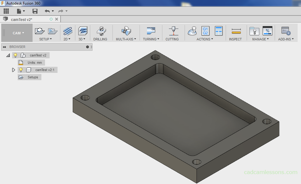
We will discuss examples of machining and parameters based on the simple cover model.

Once we have opened the model in Autodesk Fusion 360, we have to go to the CAM module to prepare the machining program.
Expand the menu on the left side of the screen (shown in the figure below) and select the CAM module.

The window should look similar to the following figure:
From the Setup menu, select the New Setup option.
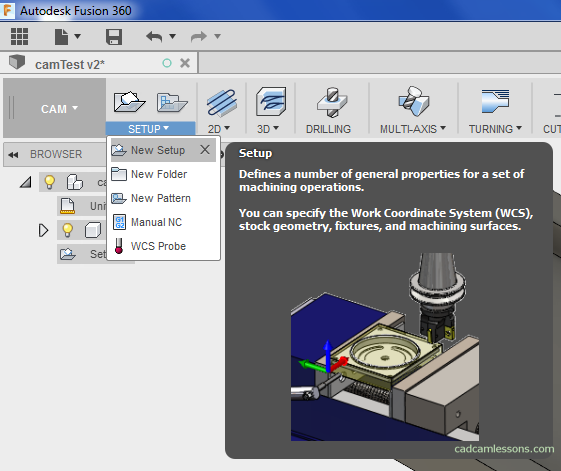
This option allows you to define machining properties, such as the origin of the coordinate system, stock or tooling. In the right part of the Fusion 360 window, a window should appear:
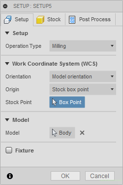
The window has three tabs: Setup, Stock and Post Process.
Now we will focus on the Setup tab.
In the first Setup section we can choose the type of machining – Milling, Turning or mill/turn, Cutting.

Let’s choose Milling.
Work Coordinate System (WCS)
The next section is the Work Coordinate System (WCS). In this section, we define the origin and location of the coordinate system that will correspond to our origin of the coordinate system defined on the CNC machine.
After expanding the Orientation parameter we have several options to choose from.
The rule is to make the Z axis as if it is moving away from the machining plane. If, as an example, we choose a 3-axis milling machine, we fix the workpiece in a vice, the Z axis should be directed towards the spindle.
Another curiosity is that in CAM systems with which I have met so far, the XYZ axes are marked in sequence with the colors red, green and blue. And RGB is one of the color space models.
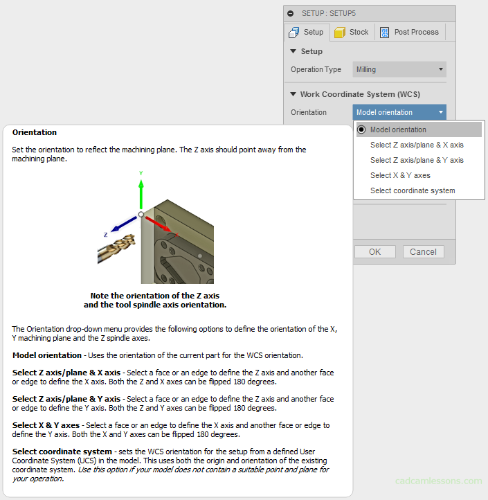
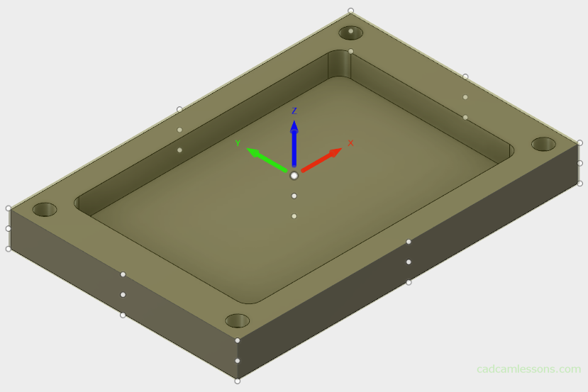
By default, the Model Orientation option is selected. There are several points on the model in which we can place the origin of the coordinate system. At the moment, we can use this option and set the origin in the middle of the stock.
In order to be able to choose points based on the stock, the option Stock box point must be selected for the Origin option.

And we indicate one of the 27 available points. In the case of simple parts, where the stock is a rectangular solid, this choice should be enough.
The next section is Model, where we mark the model that will be machined in this setup.
As we have loaded one model, it has been selected by default.
The Fixture section is responsible for the indication of the tooling (e.g. vise, jaws) – for now we will omit this.
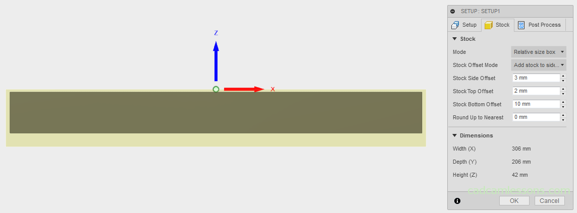
The next tab in the Setup settings is the Stock tab. In this tab, we can define the Stock.
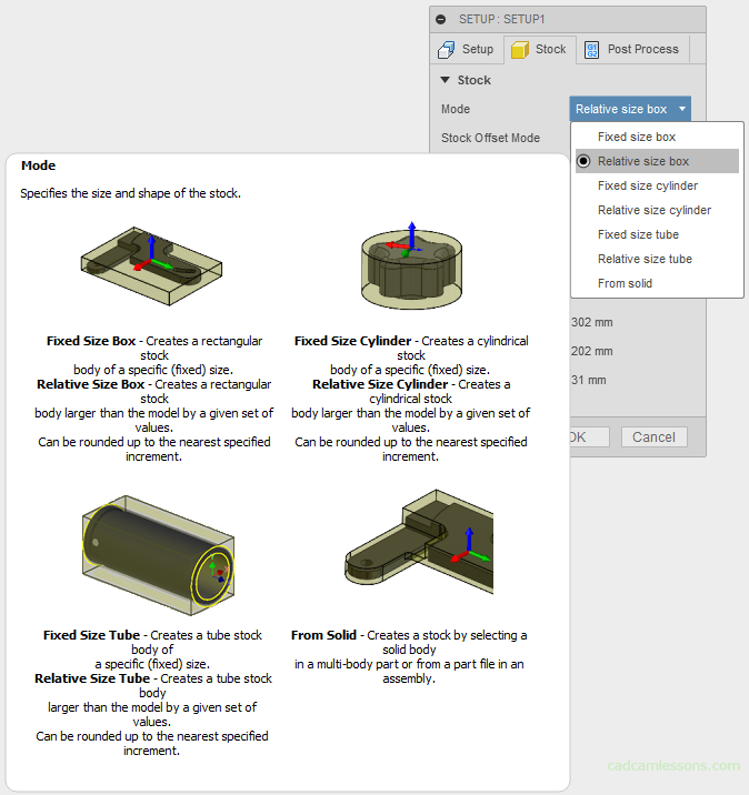
There are several options for defining a stock, but now we choose the Relative size box option for the Stock Offset Mode parameter. This option will create a cuboid shape that is larger than the model by specific allowance.
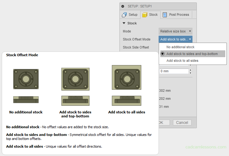
For the Stock Side Offset parameter, select the Add stock to sides and top-bottom option. This option will add symmetrical allowance and additional allowance for top and bottom of the stock.
Add a 3 mm allowance per side, a 2 mm allowance on top and a 10 mm allowance on the bottom.
The last tab is Post Process. Here we can specify the number or name of the program and add a comment to the program.
Click OK and we have the defined origin of the coordinate system. In the left part of the Fusion 360 window, Setup1 appeared.
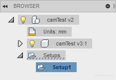
Save the work progress.
If you find my tutorials helpful, you can support CADCAMLessons:
https://ko-fi.com/cadcamlessons