If you find my tutorials helpful, you can support CADCAMLessons:
https://ko-fi.com/cadcamlessons
Linear Pattern – SolidWorks Tutorial #10
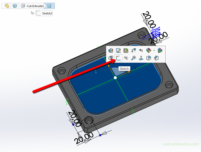
Let’s create a through hole at the bottom of the pocket. Select the bottom wall of the pocket and start sketching. Note that when you click on the wall next to the cursor the menu appears. You can also choose sketching from this menu.
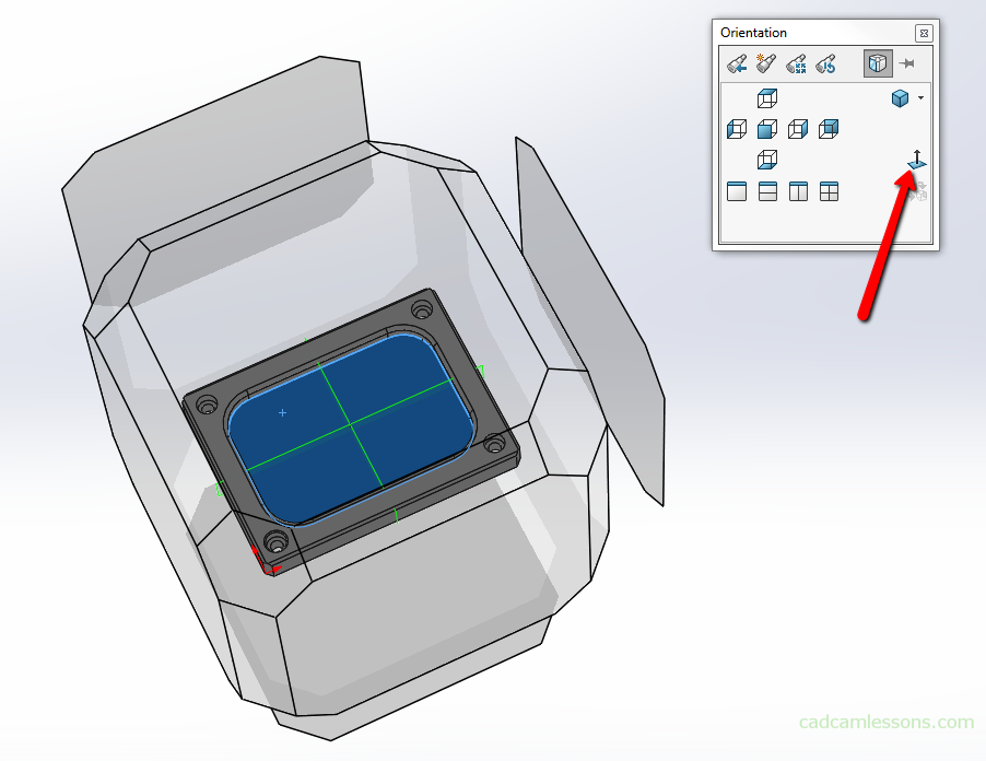
Let’s set the Normal to view. To quickly display model orientation options, we can click the spacebar and select the view we are interested in from this window.
We will now draw a circle whose center will be at the midpoint of this 25 mm radius.
Choose circle drawing. We draw the circle by selecting the center point and dragging the cursor to specify the radius, but the radius it’s not important now. We’ll dimension the circle later. For now, let’s focus on determining the center point of the circle and to do it quite efficiently, now when you move the cursor on the corner radius its center will be displayed after a while. Now move the cursor on the center of the fillet and left click to define this point as the center of the circle.
Now to specify the radius of this circle, drag the cursor to any place and click the left mouse button.
Let’s dimension this circle. Select Smart dimension, click on the circle and specify its diameter as 5 mm.
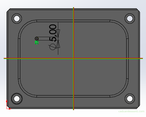
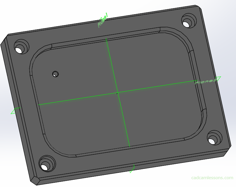
And about the fact that the center of the circle is in the same place with the center point of the fillet informs us this icon it is Coincident relation. Later we’ll get to how to set such relations yourself, but for now let’s accept the sketch and add the Extruded Cut feature and here in the End Condition field choose the option Through all to get a through hole. And accept the choice.
Let’s add a chamfer of 0.5 x 45 degrees on the edge of this hole.
And choose the Linear Pattern operation.
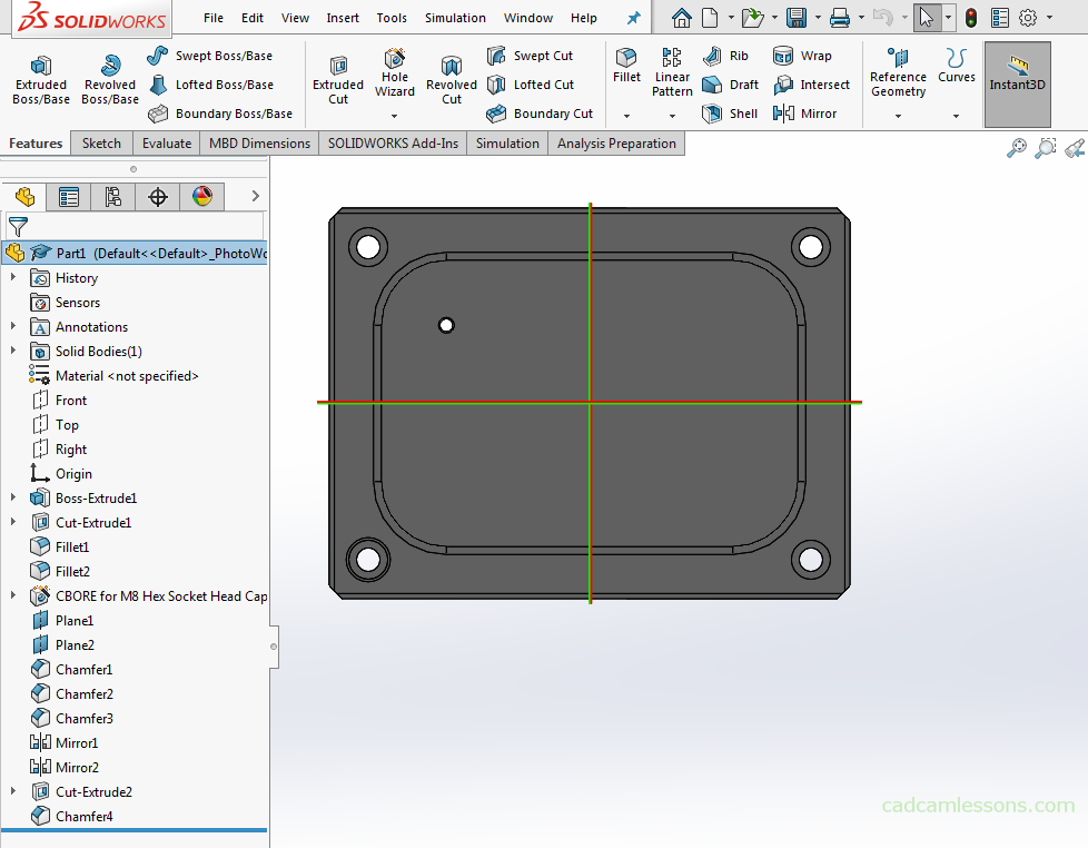
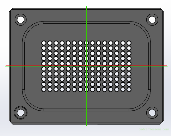
The linear pattern operation is designed to create a specific number of instances of the indicated features in one or two directions. And we will do it on the example of this small hole and chamfer. So let’s mark the hole and chamfer as Operations and walls.
As the first direction we choose line as in the drawing and we can already see the preview of the elements in a linear pattern.
As the second direction we choose line as in the drawing.
And when we look at individual options, it’s easy to understand what it’s all about.
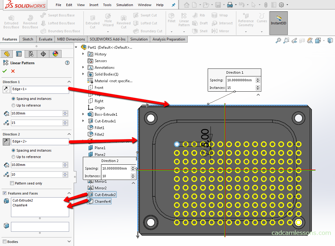
In the Direction 1 section, we specify the direction in which the instances of the operations are to appear. And we pointed this line, so subsequent instances of the operation will be arranged parallel to the indicated direction line.
Then we have the Spacing parameter. There is a value inscribed here and it is not difficult to guess that it is about the distance between individual instances. And the last parameter number of instances, specifies the number of instances of the indicated operations.
We have a similar situation in the other direction.
Of course, here in the second direction all instances from direction 1 will be repeated, not just the features initially indicated.
Ok, but with these options we can specify a specific number of instances with a specific distance between them.
And in this case I would like to receive 15 instances, evenly spaced between the center of upper left fillet and the center of the upper right fillet. And the distance between instances is irrelevant.
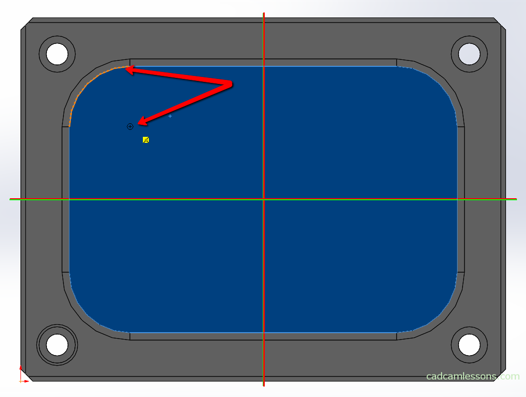
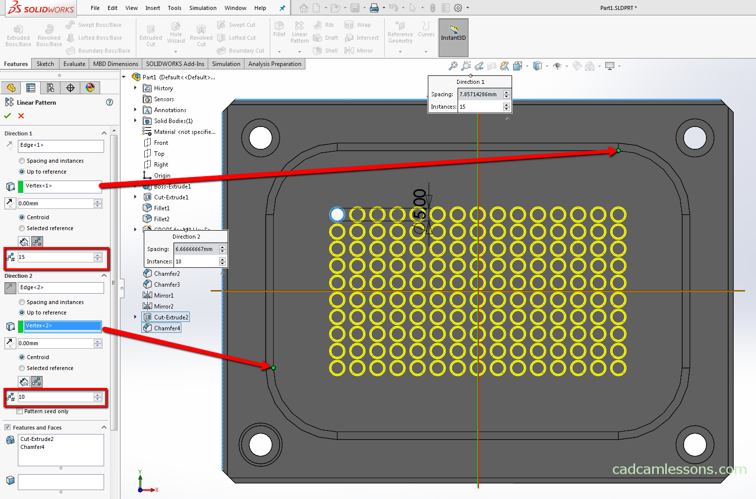
To do this, select the option Up to reference. And now the reference geometry should be determined. It can be a vertex, an edge or a wall.
And in this case the selecting the center of the upper right fillet can be difficult, because it is not displayed as in sketching when you hover over the fillet arc.
But we don’t really need the center in itself, we need the coordinate of the center of this fillet, in an axis parallel to the line defining the direction of the array.
So the end point of the fillet arc has the same value in this axis and it can be used as reference geometry.
And now if we want a specific number of instances then you should choose this option and enter 15 here.
And already in the preview we can see that the first instance has a center in the middle of the upper left fillet, i.e. as we have drawn, and the last instance in this axis have a center in the middle of the upper right fillet.
Let’s do the same in the other direction.
Select the option Up to reference, select the end point of arc as the reference, enter 10 as the number of instances.
Accept the linear pattern operation.