Tool Definition Fusion 360
Selection and definition of tools in CAM systems
YouTube: https://youtu.be/QfJNOPLcHr0
If you want to use the available in the workshop milling tools, you need to define them properly in the CAM system. In addition to the dimensions and shape of the tool, the parameters with which this tool can work in a selected material will be important.
This information can be found in the tool manufacturer’s catalog and in the case of new tools or small experience in working with this type of tool, this is the best way to choose parameters. Later, we can modify the parameters depending on the length of the tool or the method of machining.
The methodology of working in CAM systems is similar, and the machining parameters that we must determine are present in every CAM system. Understanding these parameters is the basis for further work related to machining.
Tool Library
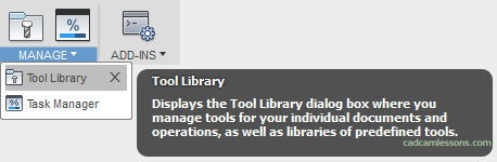
In Fusion 360, one way to define tools is to choose the Tool Library from the Manage menu.
After selecting this option, the following window will appear.
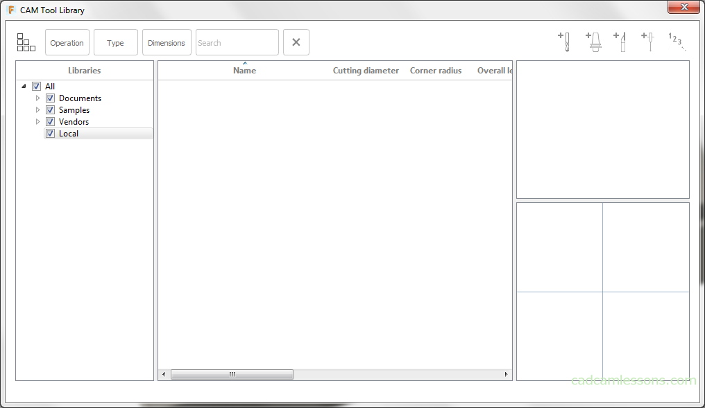
In the left part of the window we have a tool library, and in the upper right corner, a button that allows you to add a new milling tool. As for tool libraries, we have tool libraries for the current project.
These libraries will be located in the Documents tab. Libraries that we can use in every project (once we define and use everywhere) can be found in the Local tab. These libraries will be saved on the user’s computer. You can move the file with the tool library between computers.
Tools from the local library can be used in the currently open project, but we can also use them in other projects. It is worth developing a strategy for defining the tool. For example, defining tools for specific machines or for machining a specific material.
By spending some time at the beginning or remembering such a structure while defining the tool, we can create an extensive library, which will contribute to a huge saving of time when preparing machining programs. You will not have to look at the catalogs for cutting parameters every time.
New Tool Library and New Mill Tool
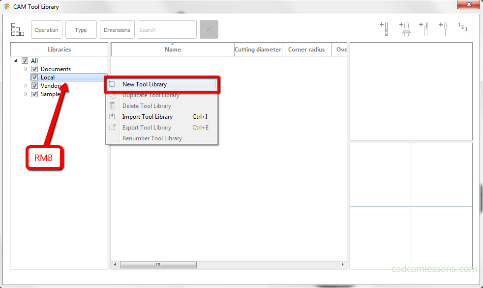
Let’s create a new tool library. Right-click (RMB) in the Local menu and select New Tool Library from the drop-down menu.
The new tool library will be called Haas.
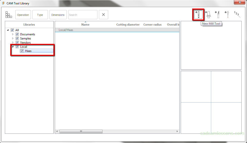
To add a tool to the library, left-click on the New Mill Tool icon.
First is General tab.
In the Description field, enter the High Feed Face Mill.
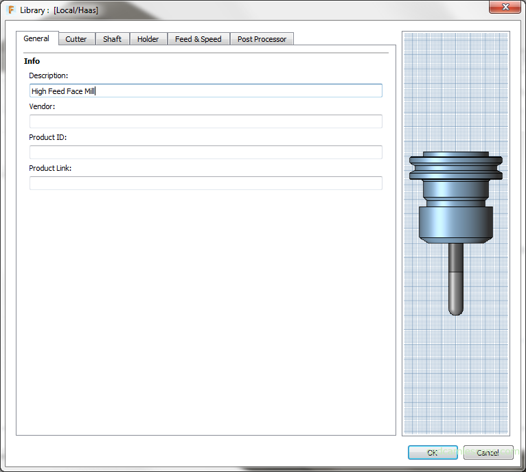
The Info section are fields in which we can enter basic information about the tool, such as description, vendor or product ID.
Next is Cutter tab.
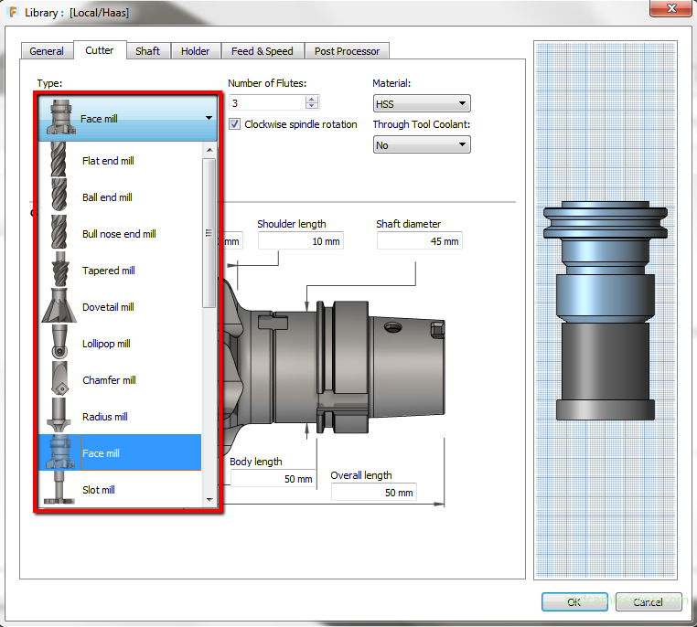
In the left part of the window, you can expand the menu with the tool types and choose the type of tool you want to define. Let’s choose Face mill.
Next to the type of tool we have the option to specify the material from which the tool is made.
Tool material in CAM systems
In the case of a “standard” approach to machining in CAM systems, the determination of tool material does not affect the generation of tool paths.
The tool will work with specific parameters that will be entered in the next fields. However, more and more CAM system manufacturers use solutions that improve and accelerate the generation of tool paths. The tendency is to use the full length of the tool, and work with a small cutting width and with high feed values. The algorithms of these solutions take into account the material from which the tool is made, and on this basis and on the basis of the machined material (in short), the values of spindle rotations and feeds are selected.
We will not be doing this in the near future, therefore at this point the choice of the tool material will not be significant, but when machining steel the most often the best choice is carbide. HSS also has its application, in my case mainly when drilling deep holes that are not tolerated. HSS drill bits allow to obtain a really good length to diameter ratio, which is difficult to achieve with carbides.
Coolanat and direction of tool rotation
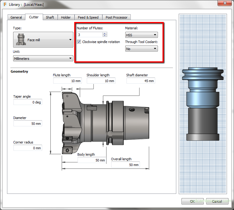
The next parameter in this section is Through Tool Coolant, that is if the machine has cooling through the spindle, and there are proper coolant channels in the tool and we want to use this option select Yes.
The next field is Units. I prefer millimeters. If you use inches, select Inches.
The next option is Clockwise spindle rotation. So if the tool rotation is clockwise, we check this option, if the tool is to rotate counter-clockwise, we uncheck this option. In many control systems this corresponds to the M3 function – clockwise spindle rotation (CW). For M3 select the Clockwise spindle rotation option or M4 – counter-clockwise spindle rotation (CCW), then uncheck this option.
In this case, check this option.
As we are already in the functions M3 and M4 in the G-code, it is worth mentioning M5, which means stopping the spindle rotation, e.g. before changing the tool or after the program is finished.
The next field is Number of flutes. Let’s enter here 5.
In the main part of the window we have parameters allowing to define the dimensions of the tool.
Fill in as in the picture below.
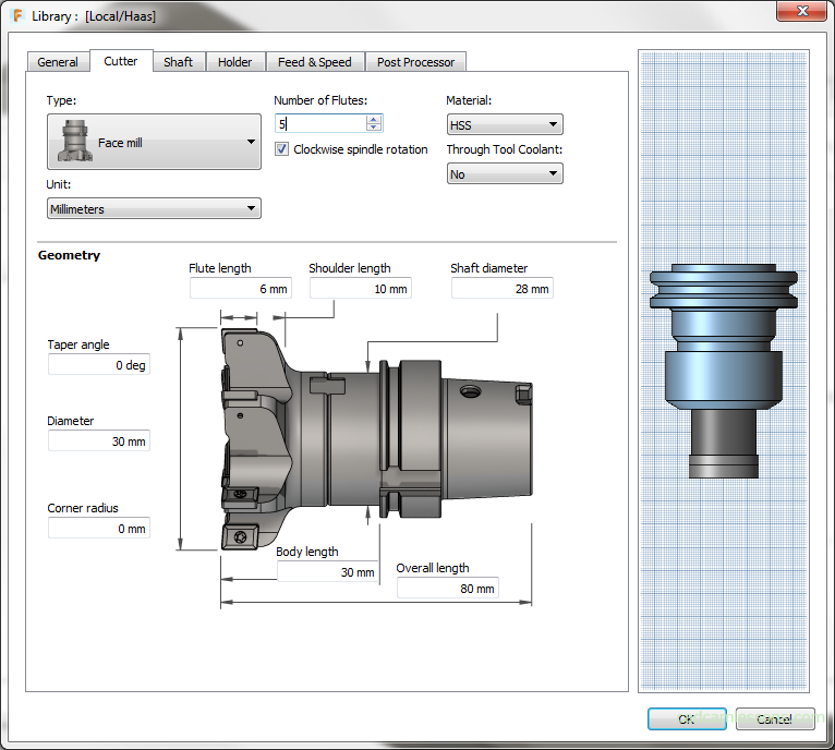
Tool geometry
Shoulder length is a parameter describing the length of the part of the tool that has the same (or slightly smaller) diameter as the diameter of the flutes.
This is important especially for end milling cutters where the length of the flute is e.g. 10 mm, but we can successfully machining to a depth of e.g. 40 mm. After exceeding the length of 40 mm, the tool from the working part passes into the gripping part with a larger diameter.
The Body length parameter is the tool length outside the holder, and the Overall length parameter is the total length of the tool. In most cases, the total length of the tool will not be important. It will be important how much the tool should be outside the holder.
Tool Shaft
Now let’s move to the Shaft tab.
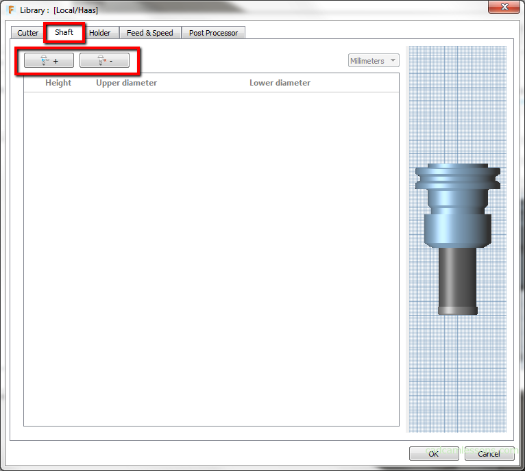
To add a new spindle click the left mouse button on the plus icon.
Now, by adjusting the parameters Height, Upper diameter and Lower diameter, we can adjust the tool shaft.
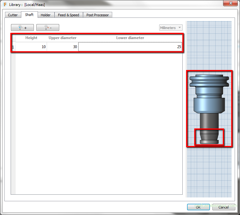
If we once again click on the plus icon, we can add another section of the shaft, which we will define over the previously created one.

To delete a section, click the button with the minus icon.
Tool Holder
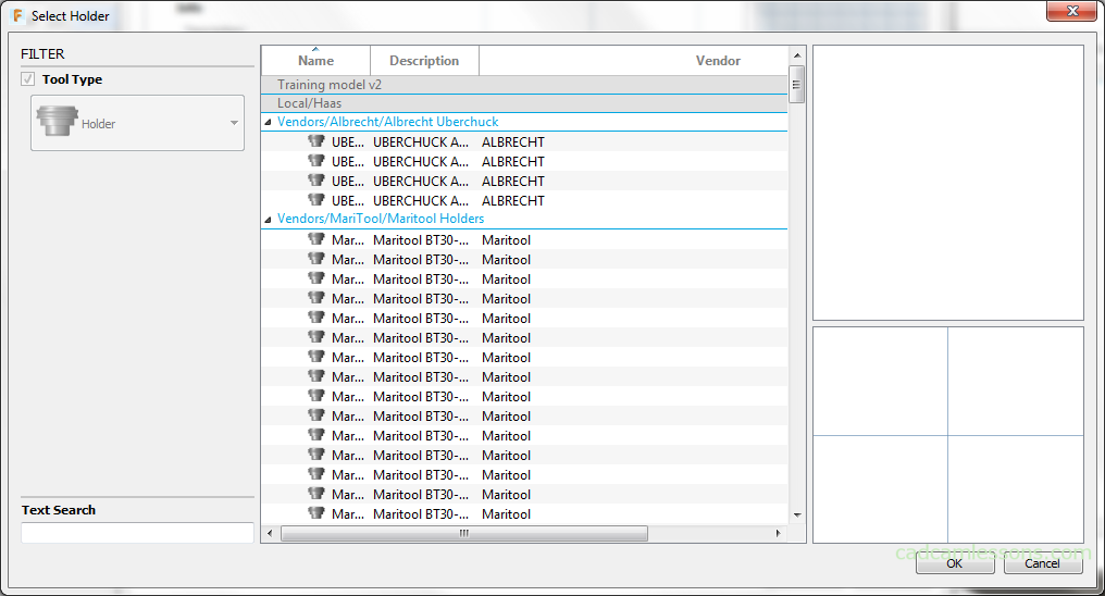
The next is Holder tab. In this tab, we can choose a holder.
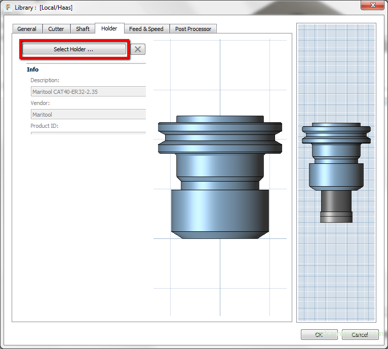
After clicking the Select Holder button a window will appear with a base of holders available in Fusion 360. It is quite a complex database, so we will definitely choose something that will be useful for us.
In the case of 2.5D and 3-axis machining, in most cases the most important will be how much the tool is outside the holder.
We will discuss the next tabs in the next lesson.
If you find my tutorials helpful, you can support CADCAMLessons:
https://ko-fi.com/cadcamlessons