If you find my tutorials helpful, you can support CADCAMLessons:
https://ko-fi.com/cadcamlessons
Feed Optimization Fusion 360
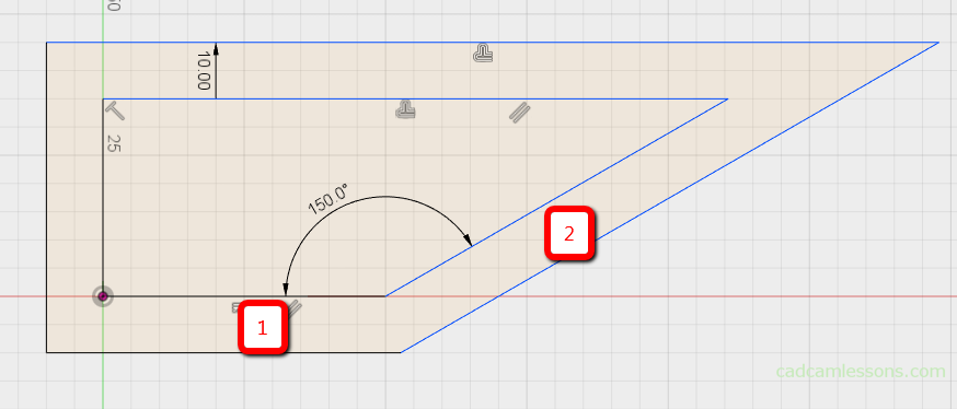
As for the Passes tab in the 2D Contour processing, we have yet to check the Feed Optimization section. This tab allows you to apply smaller feed values at the corners of the geometry, which can be very useful. In the corners of the geometry, the tool is more loaded and exposed to faster wear and even damage.
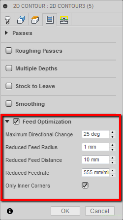
The first parameter, Maximum Directional Change, is responsible for the selection of geometry corners to slow down the feed. Depending on how big the change of the angle will be.
In the example shown in the figure above, the change in the angle of geometry on which the tool will move is 30 degrees. That is, the change in the angle between segments 1 and 2 of the above geometry.
And if the Maximum Directional Change parameter is less than 30 degrees, it means that we want to use slower feed in this corner.
If the parameter value is changed to 31 degrees.

In the corner in which the angle change is 30 degrees, the feed will not be reduced.
But all the time the feed will be reduced in the other corners, in which the change in cutting direction is greater than that entered in the Maximum Directional Change parameter.
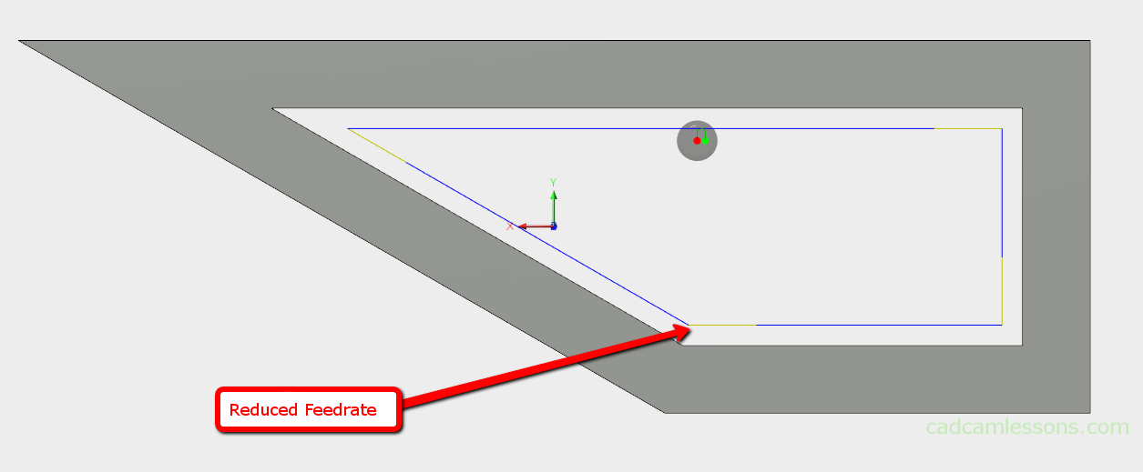
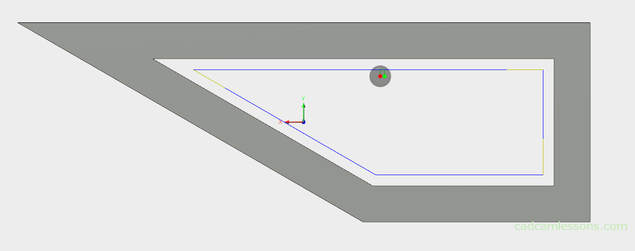
Pay attention to the corners in which the feed rate will be reduced. Tool path moments before entering such a corner has a different color. It simply means that at this point the feed rate will be reduced, and the distance from the corner at which the tool will work with reduced feed rate corresponds to the Reduced Feed Distance parameter. And reduced feed rate value will be taken from the Reduced Feedrate field.
The Reduced Feed Radius parameter allows us to apply a reduced feed value at the corners in which the tool path is rounded. In such corners, the angle change of the cutting direction is small and it is difficult to meet the condition from the Maximum Directional Change field. Here, you can simply specify the radius of the tool path corner in which the reduced feed is to be applied.
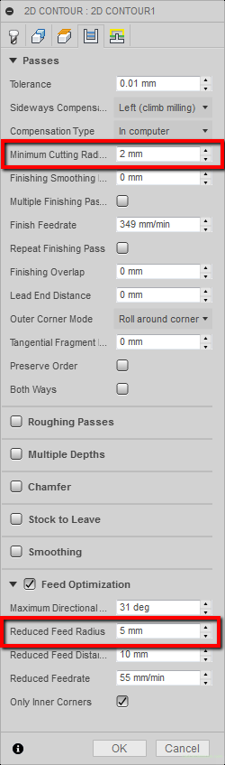
The radius of the tool path rounding in our example is 2 mm. To obtain a reduced feed, we must enter a value greater than the rounding value of the tool path, e.g. 5 mm, in the Reduced Feed Radius field. Then all radii less than 5 mm will be machined at the feed specified in the Reduced Feedrate field.
The Only Inner Corners option selected will apply feed optimization only to internal corners.