
If you find my tutorials helpful, you can support CADCAMLessons:
https://ko-fi.com/cadcamlessons
FreeCAD Tutorial – Quick Start – Basic 3D Modeling
Video below!!!
This article could be a FreeCAD ebook. Let’s get started!
YouTube: https://youtu.be/T8Z_imCbk34
In this tutorial we will prepare simple 3D model and after that you could be able to create simple parts by yourself. Let’s start!
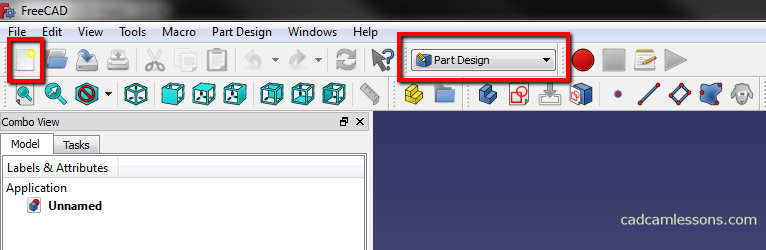
To start modeling in FreeCAD, select File | New and choose the Part Design module from the drop-down menu.
Sketching a rectangle
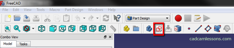
We start with sketching a rectangle. To create a sketch, click the Create a new sketch button.
The next step is to select the sketch plane.
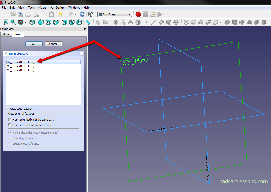
Select the XY plane and click OK.
Note that for sketching time, we switched to the Sketcher module. To draw a rectangle, select the Create rectangle in sketch button.
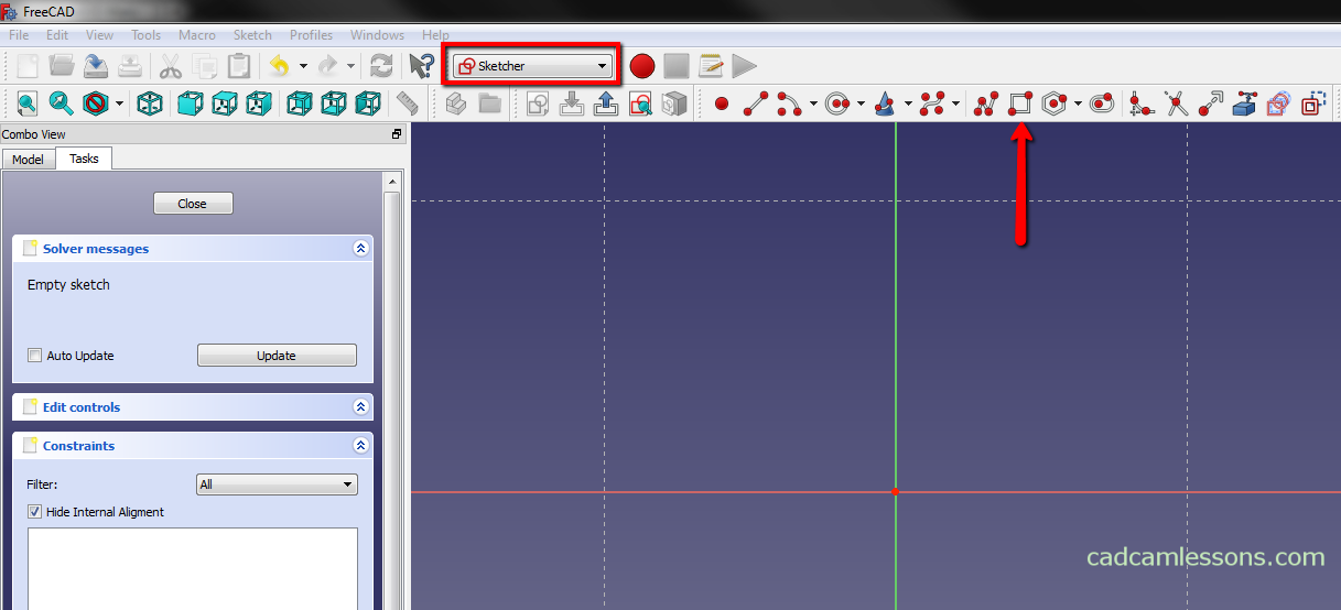
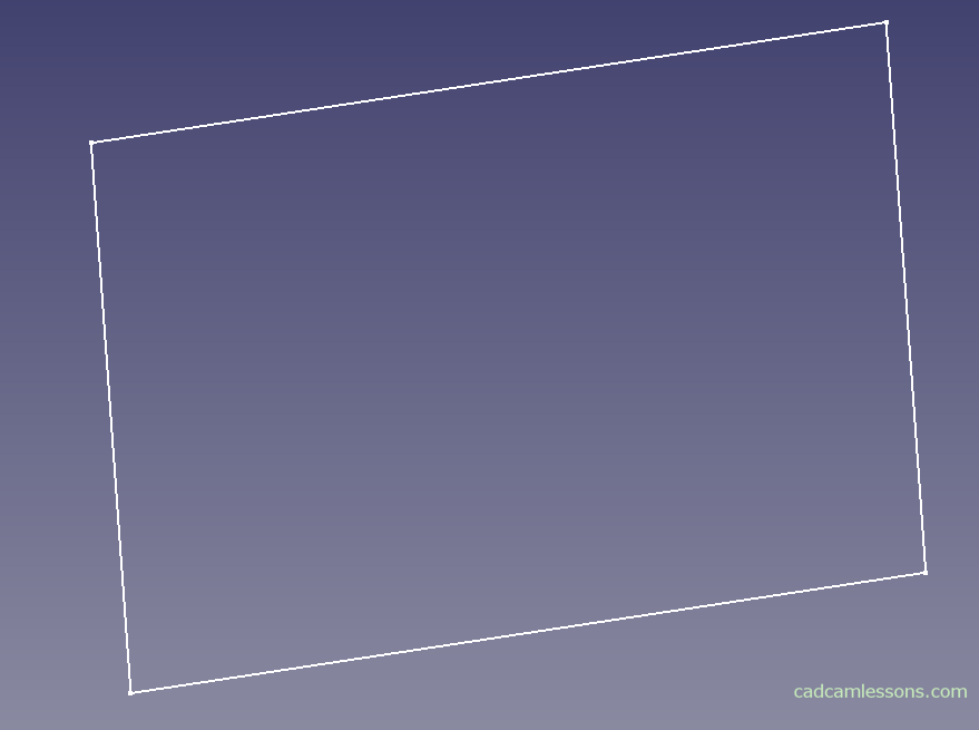
Draw any rectangle.
The rectangle drawing command is still active. By clicking the right mouse button in the work area we turn off the active command and we can proceed further.
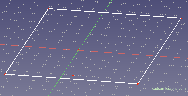
If we accidentally rotate the sketch and it will not be visible as in the above figure, rather just like in the figure below.
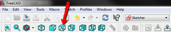
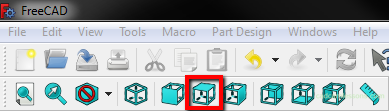
And we want to set it in the top view, click the Set to top view button.
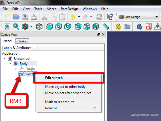
And if we leave sketch mode, but we would like to edit an existing sketch. From the Model tab from the right part of window, expand Body and double-click the left mouse button on the sketch you want to edit or right-click and choose Edit sketch from the menu.
This information may come in handy as soon as we start working with FreeCAD and the drawing will “run away” somewhere or turn around, or if we accidentally leave the sketch.
After creating the first solid I will discuss navigation methods. How to rotate, zoom etc.
We have a sketch, but it is not oriented to the origin of the coordinate system and is not dimensioned.
Constraints
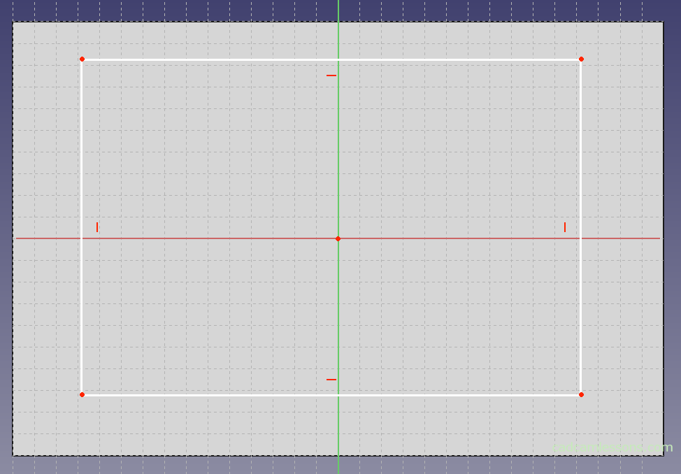
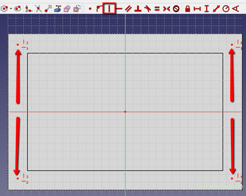
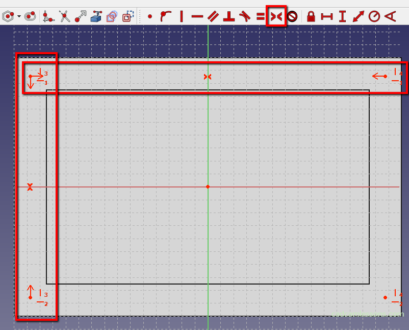
At the beginning, we set the sketch symmetrically to the XY axis.
With the Ctrl key pressed, select the two vertices on the left and right sides of the Y axis and the Y axis.

Then select the symmetry constraint.
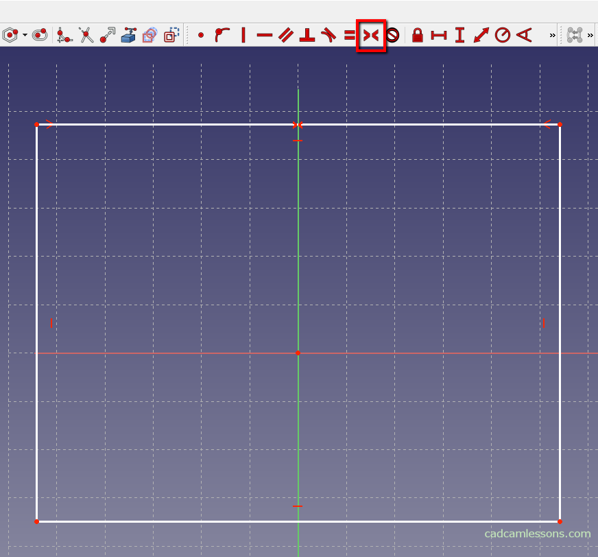
Repeat for the vertices below and above the X axis.
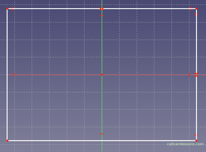
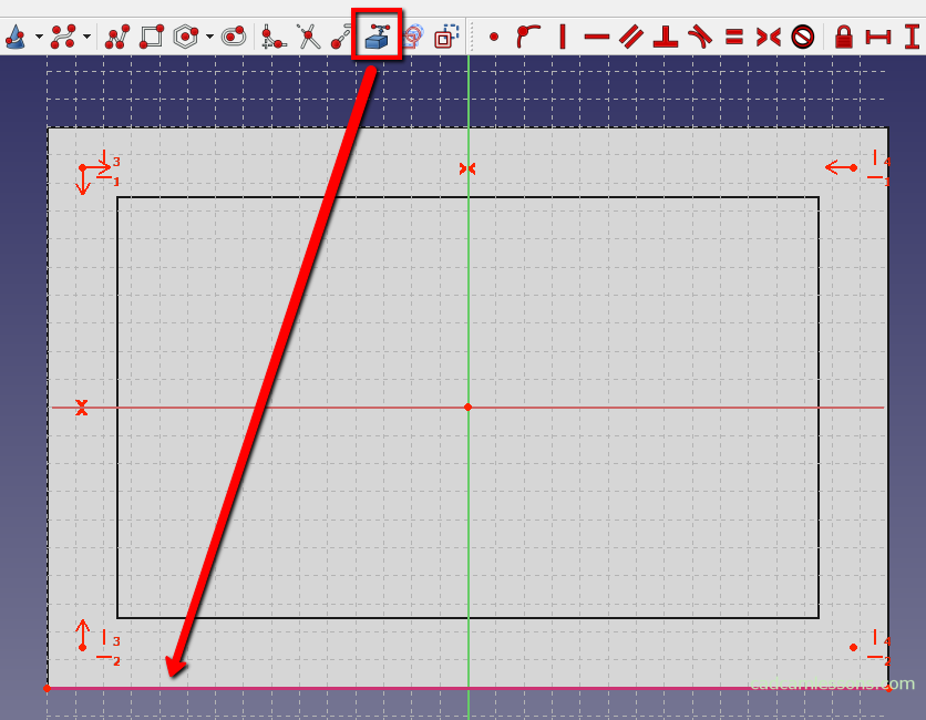
Now we can dimension the rectangle.
Dimensions
Dimensioning in FreeCAD works so that first we can choose the feature or distance that we want to dimension, and then the type of dimension. Or first the type of dimension, and then we indicate what we want to dimension.
Choose the horizontal distance.
Then select the upper side of the rectangle or two vertices lying at the ends of this side.
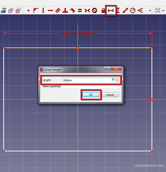
A window will appear in which you enter the dimension value. In the Length field enter 300. Optionally, we can name this dimension.
Then select the vertical distance to dimension the vertical side of the rectangle.

The same window appears as before and enter 200 in the Length field.
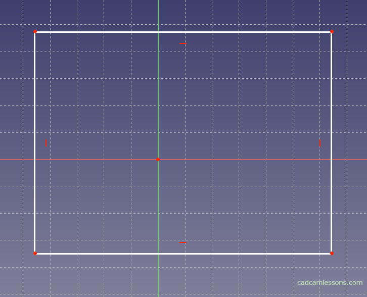
We have a rectangle drawn with dimensions 300 x 200, the center of which is at the beginning of the coordinate system.
We can finish sketching. From the panel on the right side of the window, click Close.

Extrude – Pad a selected sketch
The drawn rectangle will be used to create a solid. However, before we do so, there are a few things that can help you navigate.
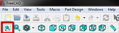
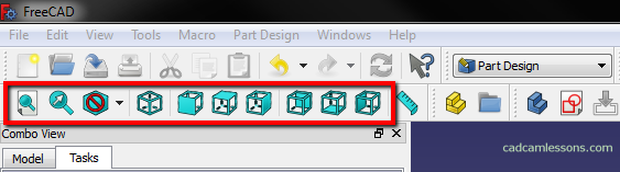
It may happen that the sketch will “hide” somewhere. We can use the mouse wheel to zoom in and out, but this will not give us confidence that we’ll find the sketch. An easier way is to use the Fit the whole content on the screen. It is located under the button shown in the drawing below.
Now the geometries are found, but it may turn out that they are shown in a rather “strange” position.
It would be much more convenient to work if we were looking at the 2D geometry in a top view. There is an easy way to do this. Just select the option Set to top view.
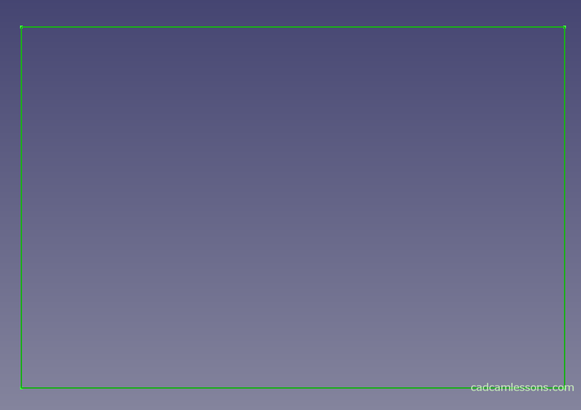
We should get a view as in the figure below.

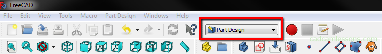
To add a sketch extrude we must remember to be in the Part Design work bench. For example, when we closed FreeCAD and reopen the file, the environment could switch to Start.
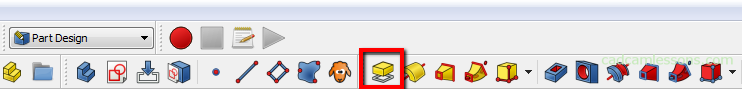
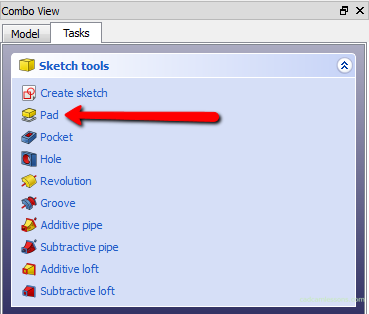
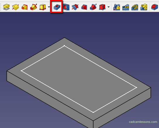
As we are already in the Part Design workbench, to create a solid, select the option Pad a selected sketch by clicking on the button shown in the drawing below.
We can also double-click on the sketch (so that all of it is marked in green).
And then, from the panel on the left, you can choose the option Pad.
The Pad a selected sketch button also requires selection, but for now we have only one geometry, so FreeCAD automatically detected what you want to extract.
In the panel on the left side Pad parameters appeared.
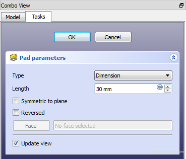
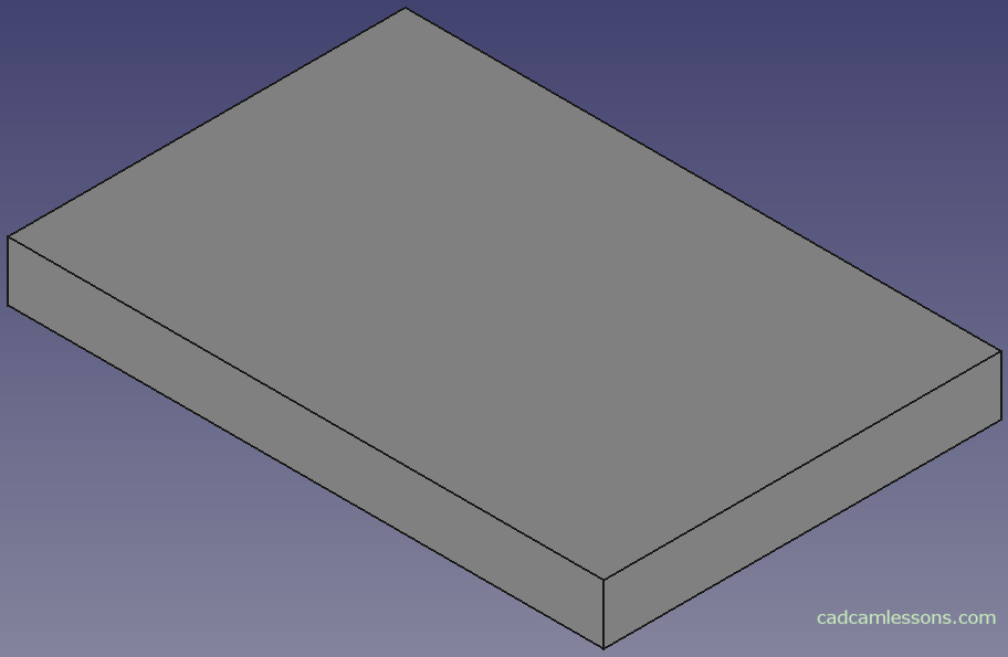
For Length, enter 30 mm and click OK. We can also accept by clicking the Enter key on the keyboard.
However, if we typed something wrong and it would be necessary to edit the pad operation, then in the left panel, in the Model tab, expand the current file.
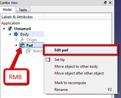
Right-click on the Pad and select Edit Pad from the menu.
In this way, we already know how to add a pad operation and how to edit it.
Navigation
We already have the first solid modeled in FreeCAD. For now it is a rectangular prism. And on its basis I will talk about navigation in FreeCAD.
The first thing is that we can choose one of the navigation styles.
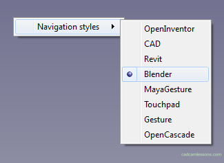
By right-clicking in the work area a menu with navigation styles will appear. The Blender style suits me the most and I will present this style.
By scrolling, we can zoom in and out the model. By pressing the roll (or the middle mouse button) we can rotate the model.
With the roller held down and holding down the Shift key, you can move the model.
The views, which buttons are available in the main menu, will also help.
Or in the View | Standard views.
I think that for the beginning this information is enough and we can go further.
Now I will show you how to make a pocket and how to add geometry on a model that will be used to make a pocket.
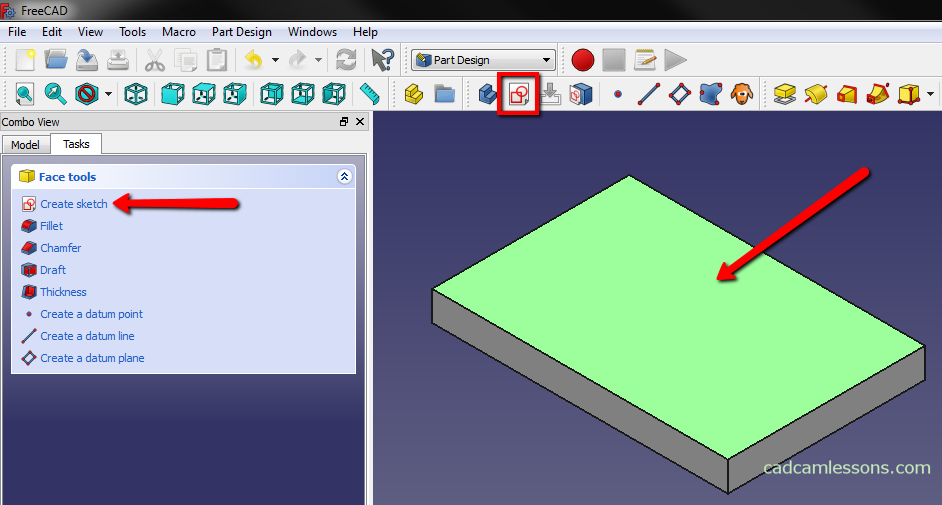
At the beginning, we must create a new sketch. We can first select the wall on which we want to create a sketch, then select the option Create a new sketch or first select the option Create a new sketch, and then select the wall on which we want to create a sketch.
Then, draw any rectangle.
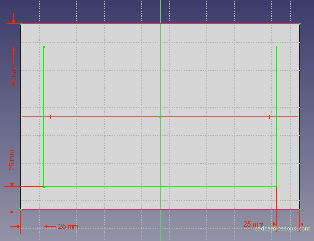
We assume that we want the pocket to be offset from each side of the rectangle by 25 mm. At this point, the pocket can only be dimensioned relative to the axis of the coordinate system. We know the dimensions of the rectangular prism, so it would be easy to dimension the pocket properly.
However, there is an opportunity to show the next function – Create an edge linked to an external geometry.

After selecting this function, we can indicate the edges that we will use as references in the current sketch. Select this function and indicate the long sides of the rectangle.
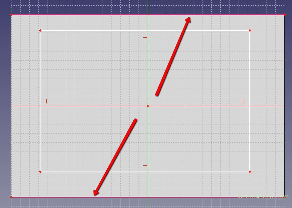
Now we can dimension in relation to the points from new lines.
Add dimensions as in the drawing below.
After adding dimensions, close the sketch. Select the Create pocket from selected sketch option.
In the left panel, select Dimension as Type, and enter 10 mm in the Length field.
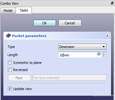
In this way, we get a pocket from the sketch.

Holes
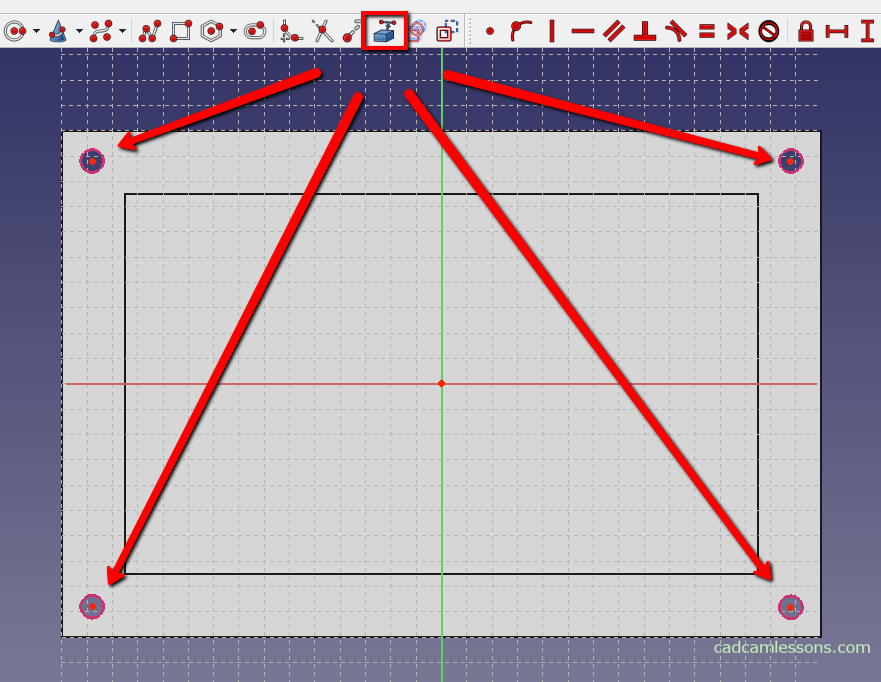
Now, we will make holes in our model. Add a new sketch on the top panel. Draw four holes in the corners of the model, similar to the figure below.
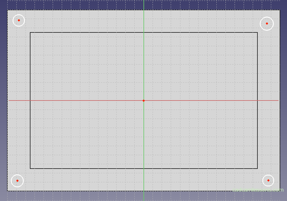
To properly orient the holes, we could dimension each hole relative to the origin of the coordinate system.
But there is a faster way and opportunity to get to know new functions. Holes lying along the long sides, we can align with each other, using horizontal constraint, so that they lie on the same line.
With the Ctrl key, select two points corresponding to the hole’s centers and select the option Create horizontal constraint on the selected item.
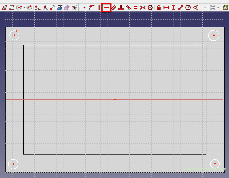
Repeat the same for the holes along the bottom edge.
For holes along the short sides of the rectangle, use the vertical constraint option. With the Ctrl key, select the two circle centers on the left and use the Create vertical constraint on the selected item.
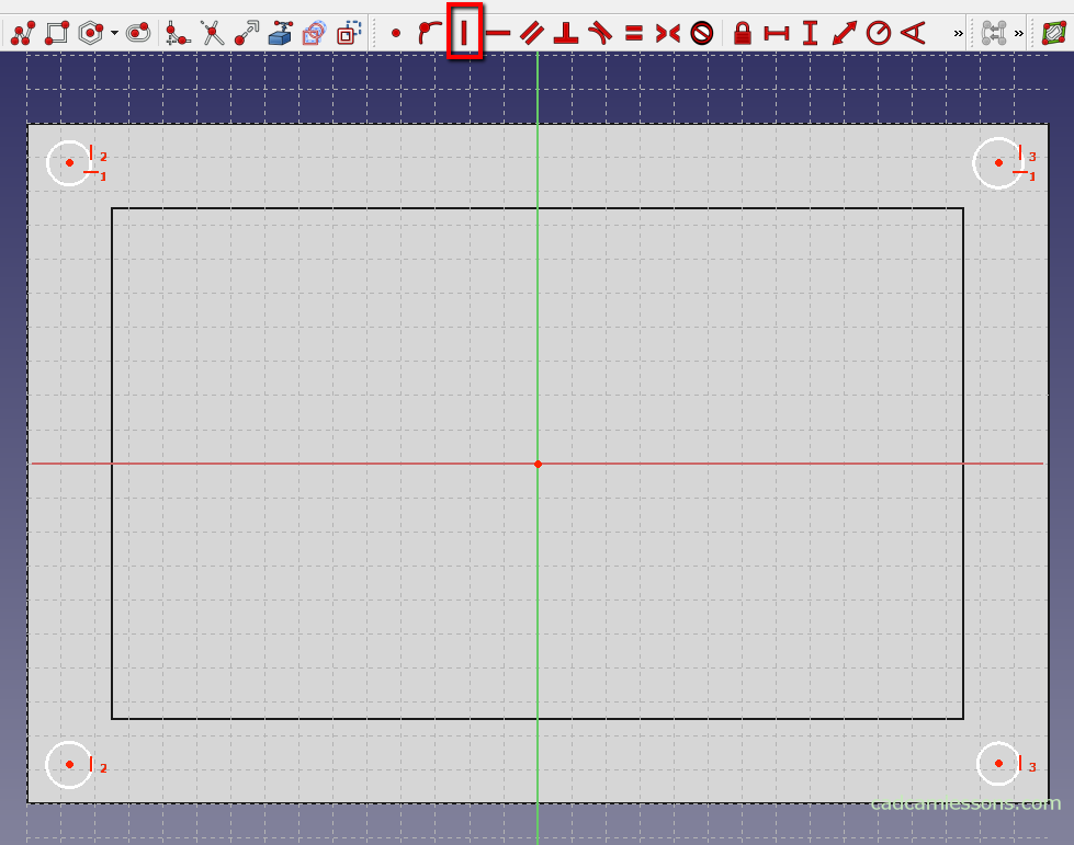
Repeat for the holes along the right edge.
The holes are already partially oriented with respect to each other. Now we have to dimension them relative to the edges of the model.
Use the option Create edge linked to an external geometry to convert two edges of the model to the sketch.
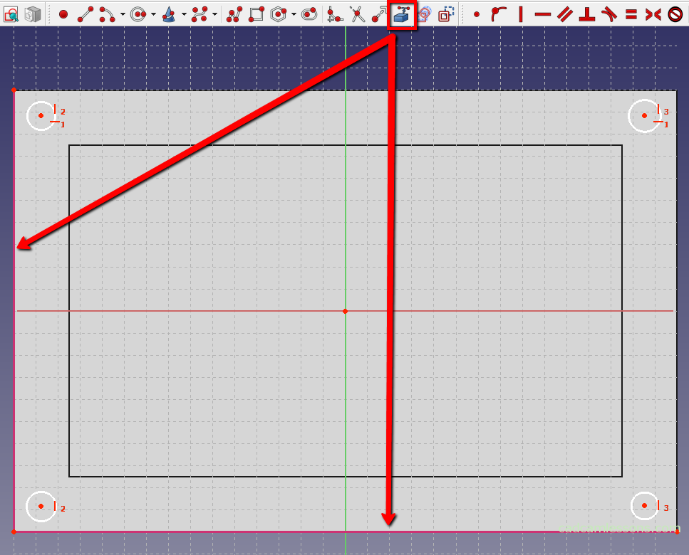
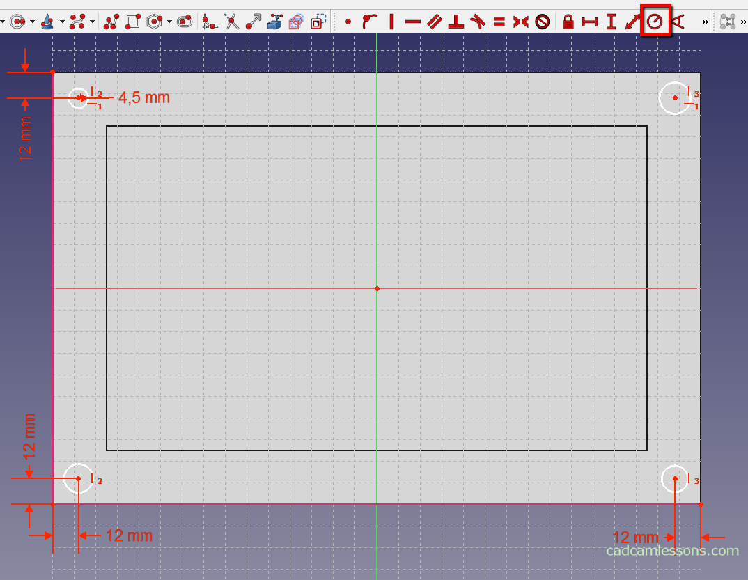
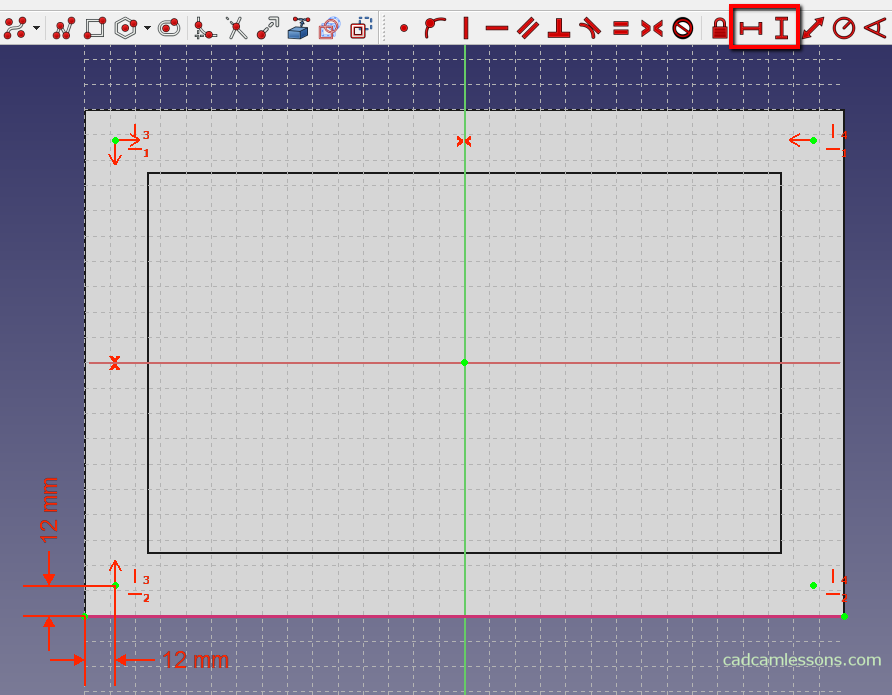
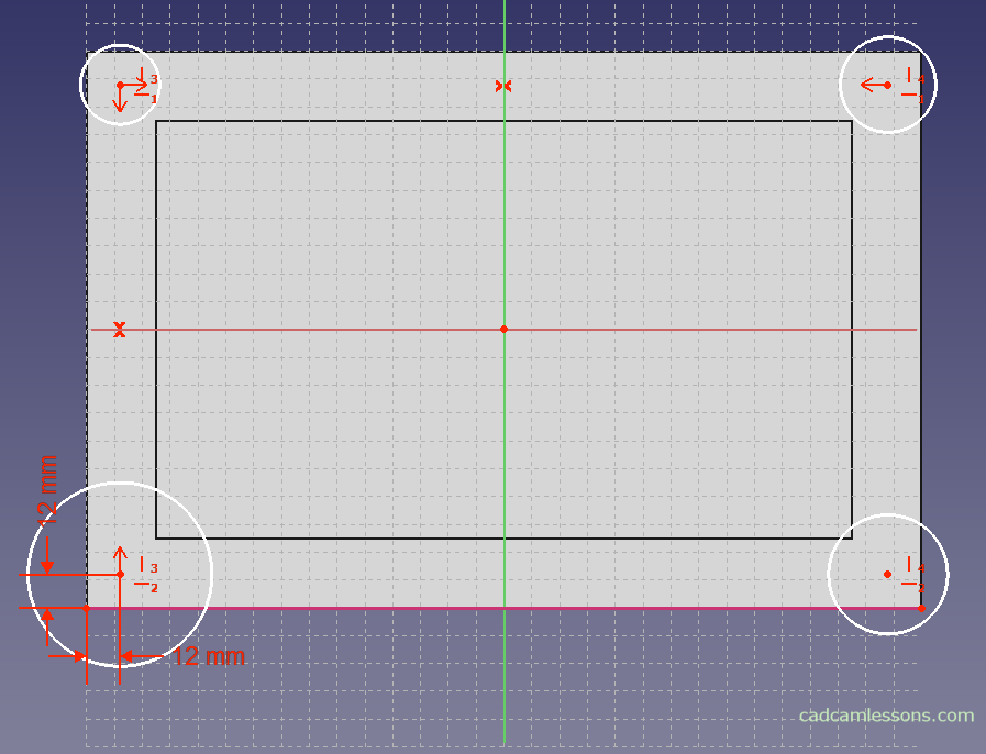
Now let’s add dimensions so that the hole centers are offset 12 mm from the edge. And using the option Fix the radius of a circle, we can dimension the radius of one of the circles. Let’s take a diameter of 9 mm, so the radius will be 4.5 mm.
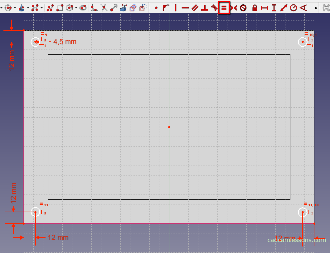
We have only one circle dimensioned. What about the others?
With the Ctrl key, select four circles, and then use the option Create an equality constraint between two lines or between circles and arcs.
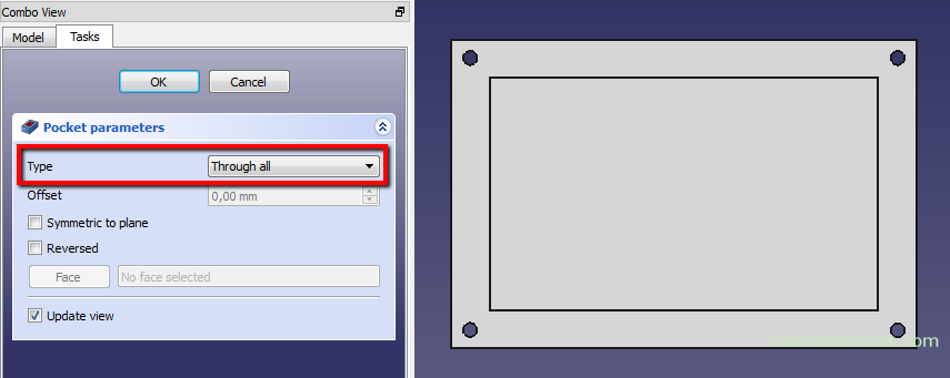
The sketch is complete now. We can now add holes in the model based on the sketch. At the beginning, use the Create pocket with the selected sketch option for this purpose.
In the panel on the left, as Type, select Through all and click OK.
Let’s add a new sketch. Draw circles with a diameter of 15 mm, the centers of which will as the same places as in circles with a diameter of 9 mm. So the option Create edge linked to an external geometry that will allow you to convert the four previous circles.
As a result, drawing the next four holes will be easier. Let’s choose the option of drawing a circle and as the center of the circle, indicate the centers of smaller circles. Thanks to the fact that they are converted to a sketch, we will do it without a problem. Then we dimension one circle. Set its radius at 7.5 mm and use the equality constraint.
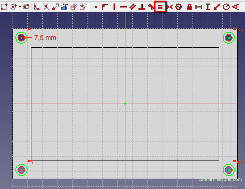
Close the sketch and add the pocket operation. For Type, select Dimension and enter 8 mm as Length.

This is one of the ways to make these types of holes. Another way is to use the appropriate function for this purpose.
Hole Creator
Previously, I showed you how to add holes by sketching circles and using pocket option. There is another way to do it. In FreeCAD, there is the Create hole with the selected sketch option, and in other CAD systems it appears as the Hole Creator or Hole Wizard. In this example, we will add holes that we previously added by drawing a sketch using FreeCAD’s hole creator.
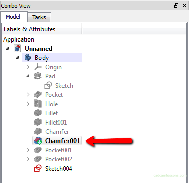
Before we add holes from the wizard, we have to remove or hide the holes that we added previously. To remove the holes, go to the Model tab in the right panel.
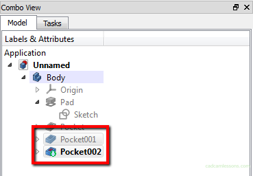
With the Ctrl key pressed, select the last two operations (the default is called Pocket001 and Pocket002) and press the Delete key. A window with a query will appear.
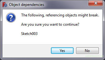
We can accept the selection by clicking Yes.
There is also a way to leave these holes. We can hide these operations and move to the moment before these holes were added.
To do this, click the right mouse button on the operation in front of the holes and select the option Set tip.

This will suppress all operations below that indicated.
To use the Create hole with the selected sketch, as the name suggests, we need a sketch. The easiest way is to add 4 points offset 12 mm from the edge of the rectangle (although the points themselves are not enough, but about that in a moment).
Add a new sketch on the top wall.
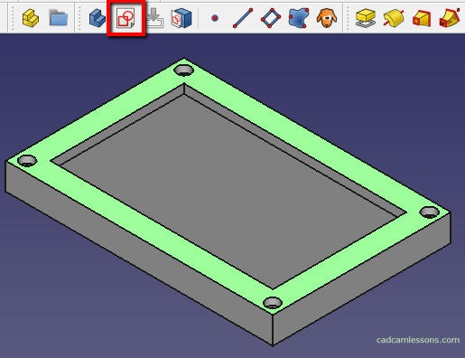
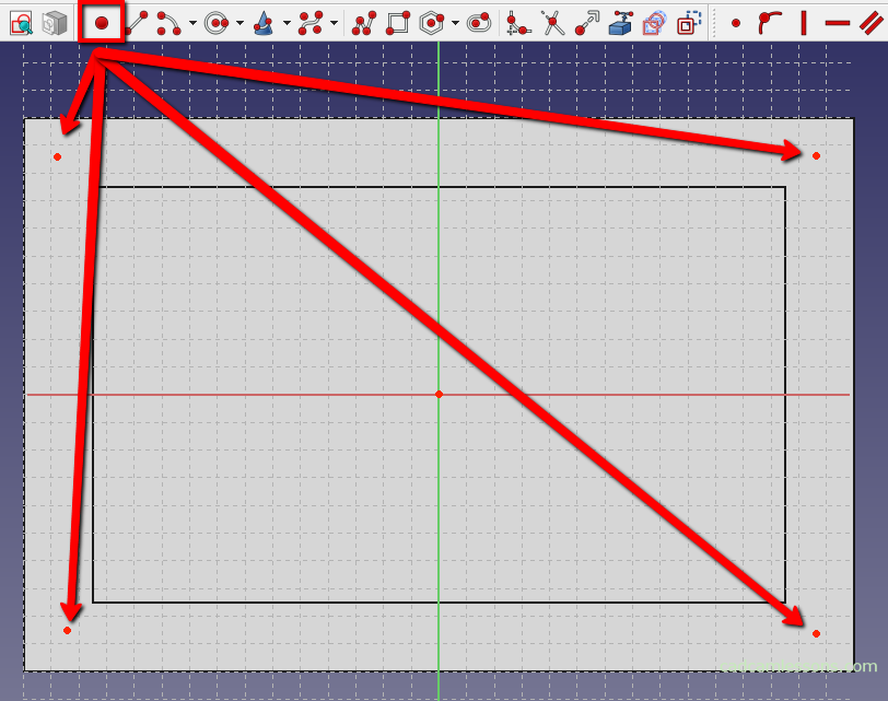
Select the option Create point in the sketch and add 4 points in the corners of the model.
For points lying along the long sides, add horizontal constraint.
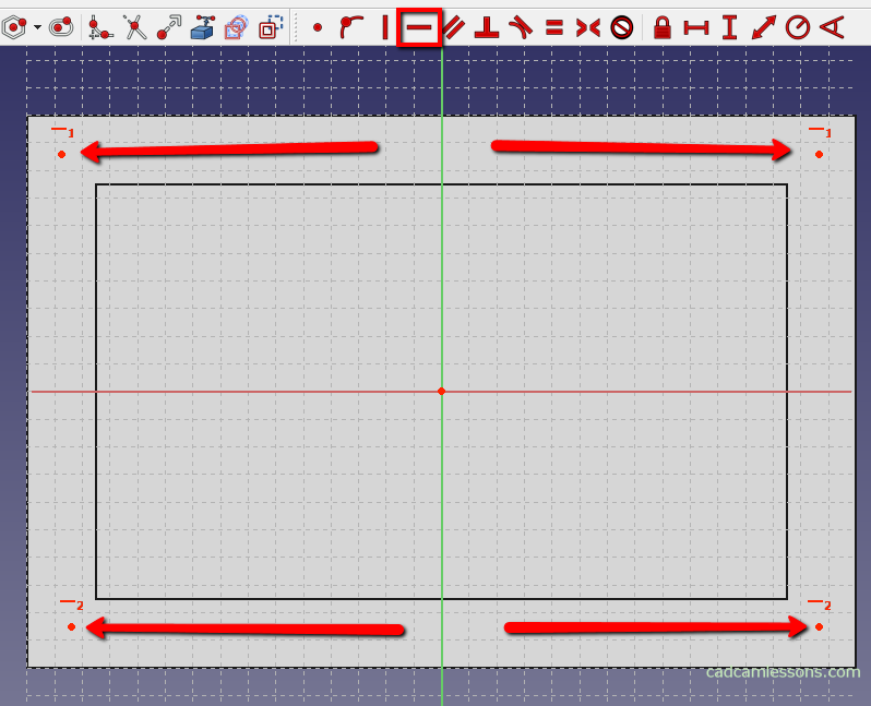
For points lying along the short sides, add vertical constraint.
Now, let’s add symmetry constraints to the points between the X and Y axes. With the Ctrl key pressed, we select two points and the axis to which they are to be located symmetrically.
Before we move to dimensioning, we still need to convert some edge of the rectangle to the sketch.
Select the option Create an edge linked to an external geometry and indicate the edge of the model.
Let’s add two dimensions, horizontal and vertical, to accurately determine the location of all points.
Thanks to the constraint, we do not have to add more dimensions. Each point is offset 12 mm from the edges.
The points themselves are not enough to automatically create holes, use them as circle centers, and draw four, any circles.
We could draw circles at once, but drawing points is faster and the drawings are more clear.
Close the sketch and select the option Create a hole with the selected sketch.
In the panel on the left we will complete the parameters as in the figure below.
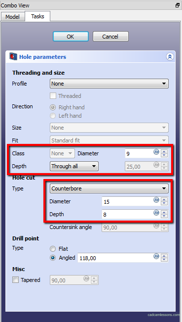
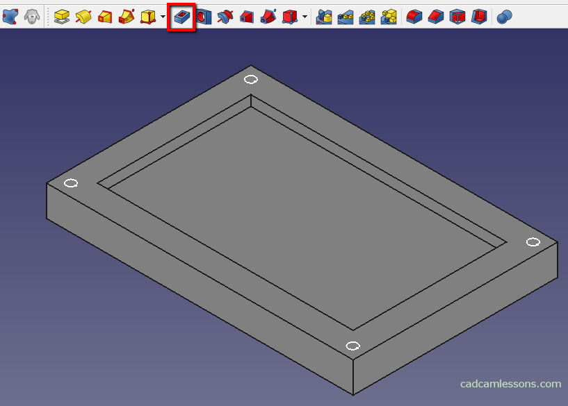
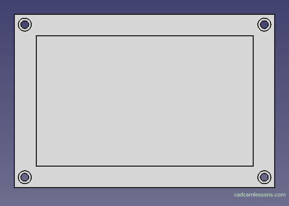
And click OK to add holes with the above dimensions.
After accepting we get holes as in the drawing below.
With the help of this hole wizard, we can also add threaded holes. We then have to choose the appropriate option from the Profile parameter. In the Size parameter, we define the thread size, in the Depth parameter we define the hole depth. Selecting Through all for the Depth parameter, the hole will be executed through it, and selecting the Dimension option, you can enter the hole depth in the field next to it. This post was mainly intended to show that there is such a thing in FreeCAD and how to start with it.
Fillet and Chamfer
Add to our model fillets and chamfers on the edges.
Fillet
With the Ctrl key pressed, select the four vertical pocket lines and select the Make a fillets on an edge, face or body.
In the window on the right, we can specify the radius value. Enter 20 mm and click OK.

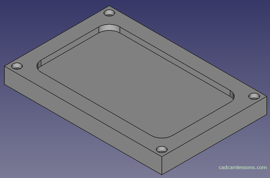
We will get something like in the picture below.
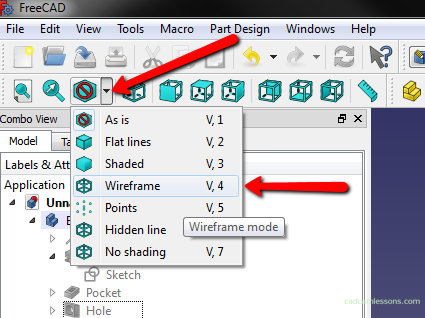
We will now add the fillets for the top and bottom edges of the pocket. In order to easily indicate the edges, you can switch to the wireframe view.
In the main menu, expand Draw Style and select Wireframe.
In this view, the selecting edges is easier and faster. Select the lower and upper edge of the pocket.
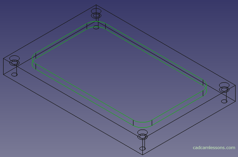
Add a 4 mm rounding and switch the Draw Style to the first option, As is.
Chamfer
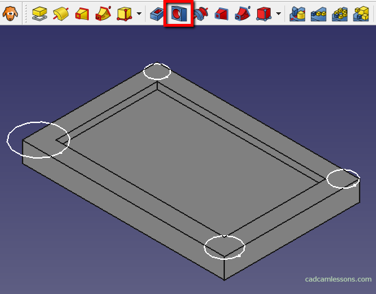
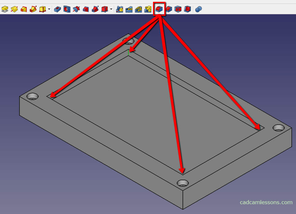
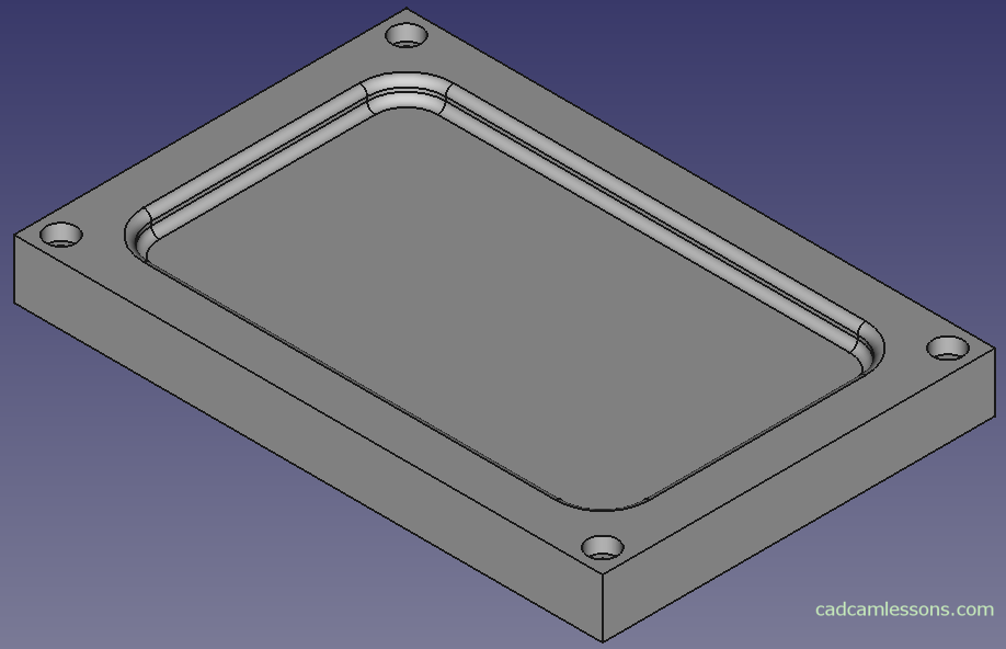
Now add the chamfers for the selected edges. With the Ctrl key pressed, select the edges as shown in the figure below and select the option Chamfer the selected edges of a shape.

Set the chamfer size to 5 mm and click OK.
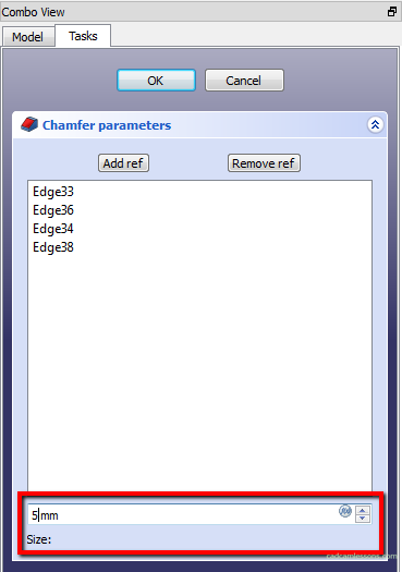
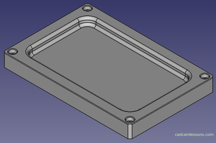
We get:
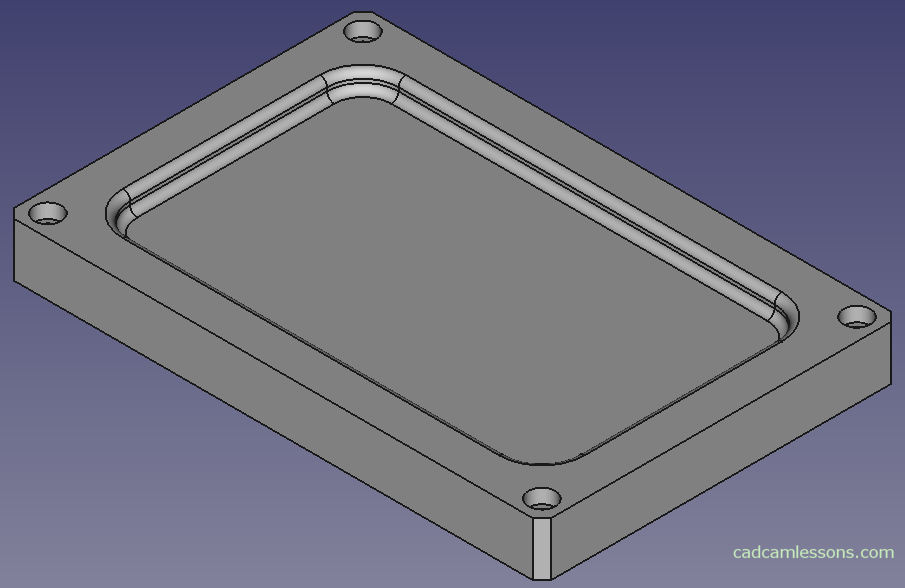
For the edges marked in the figure below, add a chamfer of 1 mm.
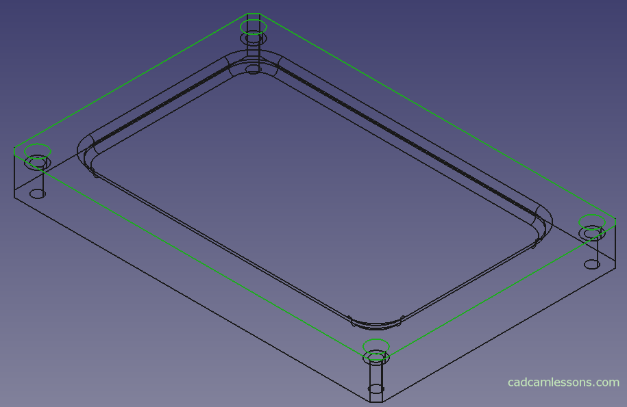
We get:
The model is ready. We went through the basic issues related to the modeling of simple parts. The options you learned should already allow you to create simple models yourself.
I will show you how to export it to STEP format so that it can be opened in other system, e.g. Alphacam.
In the Model tab, in the left pane, we must select the last operation.
Then choose File | Export. In the window that appears, specify the name of the file and select the type of files to which we want to export (I suggest STEP with colors) and click save.
Now, this file can be opened in another system that supports STEP files.
Below, you have this FreeCAD tutorial in video format: