If you find my tutorials helpful, you can support CADCAMLessons:
https://ko-fi.com/cadcamlessons
Contour machining part 1 – Rough or finish – Alphacam
YouTube: https://youtu.be/M7RXJq12MJw
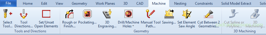
Most of the functions related to tool paths can be found in the Machine tab. Before we select the tool, the machining strategies are dimmed, only after the tool has been selected, they become active.
In our example, we will discuss the three most commonly used 2.5D machining strategies. Contour machining, pocketing and drilling.
We’ll start with contour machining. Machining of contours is the removal of material along the indicated geometry at a specify depth. So we have some 2D geometry and we mill around this geometry.
Very simple machining. In my work, there is practically no day without contour machining. A part will always appear for which you need to program the contour machining. That’s why it’s worth getting to know this strategy.
To start the contour machining strategy, select Machine | Rough or Finish.
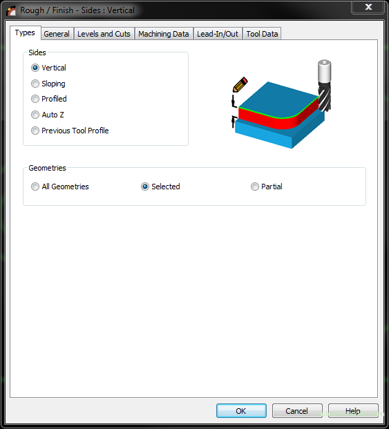
In the Sides section, we define the type of machining.
By selecting the Vertical option, we specify that we want to machine vertical walls based on 2D geometry – that is, standard contour machining. In the near future, we will choose this option most often. After machining, we will get a vertical wall.
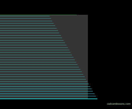
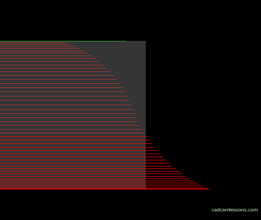
By choosing the option Sloping, based on 2D geometry, we can prepare the machining of a sloped wall at a specify angle. No need to have a 3D model.
This is done by generating the large number of paths.
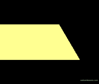
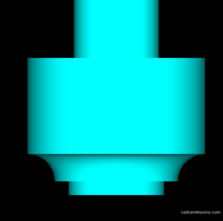
By selecting Profiled option, we can reproduce the shape of the 2D profile on the workpiece.
For example, the shape of such a profile:
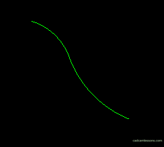
We can reproduce on the machined wall. No need to have a 3D model or a shape tool.
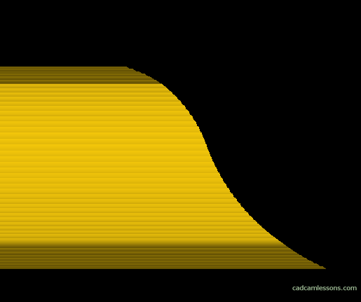
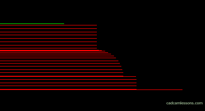
Simply a milling cutter with a small radius or a ball milling cutter, tool paths are generated with a small stepdown. Similarly to the option Sloping. The smaller the step down, the more toolpaths and the more accurate shape.
The Auto Z option allows you to read machining levels based on geometry. We must prepare the geometry properly, specifying its upper and lower levels. Then, when defining machinings, this will be automatically taken from the geometry. We’ll come back later and discuss this option thoroughly.
The Previous Tool Profile option works similar to the Profiled option. In the Profiled option, the profile that we had drawn in the workspace was reproduced. For the Previous Tool Profile option, the tool profile you previously used will be projected.
For example, we perform contour operations with a shape tool:
With this tool, we do standard contour machining.
In the next operation, choose, for example, a cutter with a corner radius and the option Previous Tool Profile. And we’ll get tool paths that project the shape of the previous tool’s profile.
This option can be useful, for example, when the shape cutter is damaged, and we will have to prepare the machining quickly with the shape representation of the tool. Or in the case of prototypes.
In the next section – Geometries, we define what we want to process.
Selecting the All Geometries option, we define that we want to apply the currently defined strategy to all geometries in the workspace.
Choosing the Selected option, we specify that we want to apply the currently defined strategy to manually selected geometries from the workspace.
And the Partial option allows us to machine a specific fragment of the selected geometry. We will discuss this later on an example.