
If you find my tutorials helpful, you can support CADCAMLessons:
https://ko-fi.com/cadcamlessons
Define Tool – Alphacam
In Alphacam, as in most CAM systems, we can define our own tools. We have the ability to define several types of tools here.
To define new tool select Machine | Define Tool.
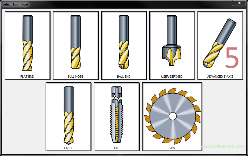
In this part of the course we will define a flat end mill. Select the FLAT END and the next window will display the parameters that can be specified when defining the tool.
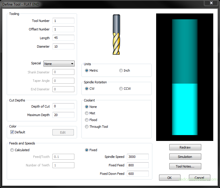
In the Tooling section, we have the parameters:
Tool Number – this is the number of the tool that will be generated in the machining program and the tool that is assigned this number in the machine controller will be used for machining.
Offset Number – this is the number that will be generated next to the tool number (or elsewhere) specifying the tool radius compensation number. This is the column number, the compensation value register in the tool table.
| Tool | Tool offset/Compensation | |||
| 1 | 2 | 3 | 4 | |
| Milling cutter 10 |
0,02 | 0,05 | 0,1 | 0,2 |
The point is that the tool can have several different compensation values. The tool compensation number 1 refers to the value 0.02, and the number 3 compensation to the value 0.1. That is, by typing a value in the field of Offset Numer we do not directly specify the tool offset value just the reference to the appropriate register in the tool table. Direct determination of the tool offset value in the CAM system would not be as effective as determining the compensation value directly on the machine during machining. After the initial machining, the CNC operator can determine the compensation value by which the current tool path should be changed in order to achieve the assumptions in the drawing. However, direct definition of the offset value in the CAM system is not without sense. There are still machines that either do not have the possibility of using tool offsets, or the use of compensation does not work properly or does not work at all. Of course, in CAM systems we do not have such an option, which is called the compensation value, but it does not mean that we can not enter this value somewhere. There are even two places where we can do it. One is the change in the diameter of the tool in the CAM system (without changing the tool in the machine). For example, a diameter of 10, change to 10.5. So the tool path will be offset by 5.25 mm from the contour and we will have an allowance of 0.25 mm per side. But changing the diameter of the tool is not convenient. It’s better to just control the allowance value. By giving the positive allowance, we move the tool path away from the contour being machined, and giving a finishing negative allowance we bring the tool path closer to the contour. So, if the compensation in the machine is not working properly, we can control the allowance value in order to obtain a dimension within the tolerance field. First, we can leave a larger allowance, measure after machining and change the value of the allowance for finishing.
Length – this is the length of the tool outside the holder. Determination of the tool length in the CAM system will be useful mainly in simulation and when creating documentation (manually or automatically) for transfer to the machine operator together with the NC program. In most cases, this will not affect to the tool paths and information on the length of the tool in the NC code may appear as a comment, but it does not affect the program.
Diameter – the parameter in which we determine the diameter of the tool. As long as we do not have to pay much attention to determining the length, the diameter is important. If you do not use the tool radius compensation, the tool path will be offset from the workpiece geometry by half the tool diameter. In addition, the compensation (in most CAM systems) can only be included in the machining of contours. So for the remaining strategies, to get accurate machining, we need to enter the actual diameter of the tool. Then, the toolpaths will be offset from the machined geometry by the appropriate value.
The Special option will be temporarily omitted.
In the Units section, we specify whether the tool dimensions are given in millimeters or inches.
In the Spindle Rotations section, specify whether the tool works at CW (clockwise rotation) or CCW (counter-clockwise rotation).
In the Coolant section, we define the cooling method, and for some woodworking machines where there is no cooling, these options are used for other settings.
In the section Cut Depths, we have two options. The Depth of Cut option determines the maximum depth at which the tool can goes down in one pass. And the Maximum Depth option specifies the maximum depth at which the tool can goes down. In practice, this can be used so that in the parameter Depth of Cut enter the length of the tool flutes, and in the parameter Maximum Depth, enter the length of the flutes plus the value length of the shank with diameter equal to tool diameter or bit smaller.
By entering the value 0, we determine that the tool can work with its entire length.
In the Color section, you can change the default tool color. Just uncheck the Default option, click the Edit button and select the color you want to apply to the tool. Tool paths prepared using this tool will also be in this color.
The last section that we will now discuss is the Feeds and Speeds. In this section we can determine the parameters of feed and rotations with which the tool will work. We have two main options: Calculated and Fixed. I never use the Calculated option, because there is lack of one more parameter that would allow me to calculate the cutting parameters. Therefore, without going into the details, I choose Fixed option. Here we have places where we can enter Spindle Speed, Fixed Feed and Fixed Down Feed.
By clicking the OK button a window will appear with the default location where you can save the tool.
Save the tool with the F10X20 name.
After clicking the Save button, a window will appear confirming that the tool has been saved.
After selecting the Select Tool option, the Alphacam tool table will appear in which our tool is already available.
From now on, we can use this tool.