
Face milling in Fusion 360
YouTube: https://youtu.be/McATsqOs74A
Face milling is one of the basic milling operations. It iis removing material from flat surfaces. Face milling is a 2-axis milling operation. This is 2.5D milling. It is simultaneous work in two axes (XY), and motion in the third axis (Z) takes place when the tool does not work in XY axes.
To select a face milling operation in Fusion 360, select the option Face from the 2D menu.

A window will appear in the right part of the main window:
Tool selection
In the first Tool tab, select the tool and specify the machining parameters.
To select the facing tool for the Tool option, click the Select button and the following window appears.

Select the created tool library (the others can be deselected). We have one tool here, choose it (either by double clicking or by selecting and clicking OK).
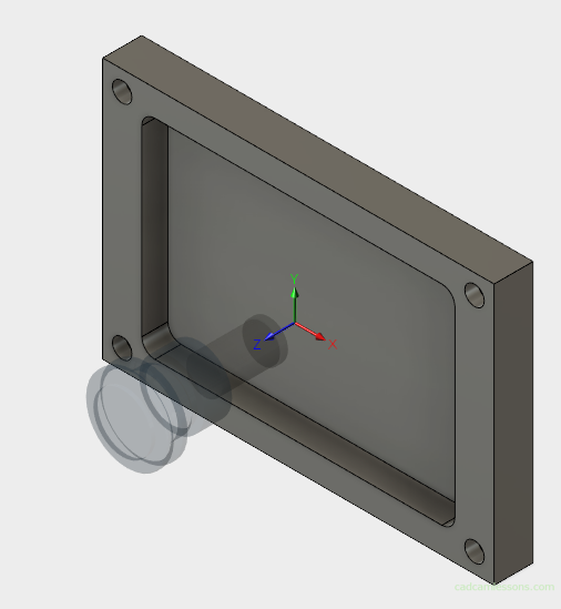
A transparent tool model will appear in the Fusion 360 window.
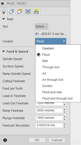
Another option is Coolant. Select the appropriate cooling for the machine on which the particular part will be machined.
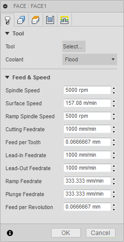
Feed and Speed
The next section is Feed & Speed. We defined these values during the tool definition. However, if we want to change it for some reason, only for this one particular operation, we can do it in this place. The changed values will be applied only in this case and it will not affect the global values defined in the tool table.
Geometry
The next tab is the Geometry tab.
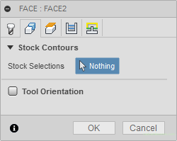
The first section is Stock Contours. A contour of the stock was marked on the workpiece model, so in this section we can do nothing. The selected geometry will determine the machining limits.

However, we also have the option of independently determining the geometry to be machined by marking it on the model.
We will omit the Tool Orientation section for now.
Heights
The next tab is the Heights tab. In this tab, set the heights on which the tool is to move between passes or between operations. And height for rapid movement (G0) and height for G1 feed.

Clearance Height
The first value is Clearance Height. This is the level to which the tool will reach at the start of machining and the machining program starts from this level. The first value in the Z axis in the machining program will be the value of the Clearance Height. The tool will also retract to this height after the operation and at this height, it will be moved to the next operation.
In the Offset field, we specify the value of Clearance Height depending on what we choose in the From field.
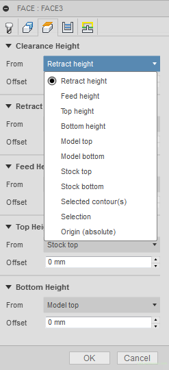
Retract Height
Another value is Retract Height. This is the level at which the tool will move between passes in a single operation. For example, if the contour is made in several passes, after the first pass, the tool will retract to the height from the Retract Height field and at this height it will move to the place where it will start the next pass.
Feed Height
The next value is Feed Height. This value defines the level at which the tool will move from the rapid movement (G0) to the feed movement (G1). The tool from Clearance Height or Retract Height will move quickly to the Feed Height and will start working with the G1 feed from this point.
The Top Height value defines the upper level of milling. From this level, the machining will start to the Bottom Height level, which defines the lower milling level.
Passes
The next tab is the Passes tab.

Tolerance
First field – Tolerance. On some CAM systems, this is referred to as chord tolerance. This is about the accuracy of matching the arcs when we want to interpolate them with short segments.
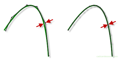
Chord tolerance is the maximum distance of the approximate sections from the arc (which will be aproximated using these segments). If you enter a small value (eg 0.001), we will get a more accurate approximation, but it will also result in a longer machining program. Some machines can not handle it. The size of the files with the machining program is rather not a problem, but short linear movements may cause the machining will not run smoothly. By entering a higher value (eg 0.1) the program will be smaller but we can get a less accurate representation of the arc. As in many cases, it is recomended to check it on the machine and select the optimal parameters.
Pass Direction
Next option is Pass Direction.
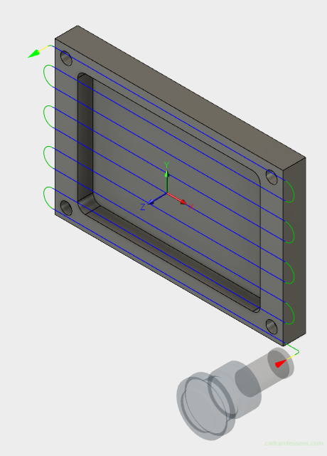
The 0 degree angle will generate tool paths parallel to the X axis.
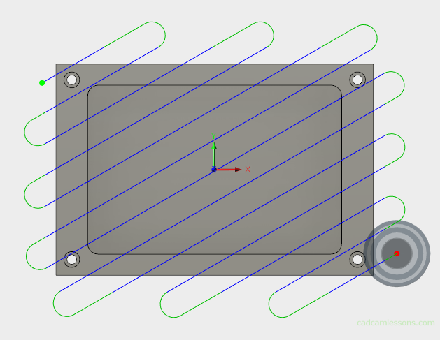
A 30 degree angle, will generate paths at an angle of 30 degrees to the X axis.
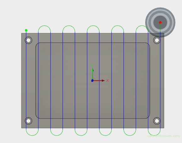
And the angle of 90 degrees will cause you to get paths parallel to the Y axis.
Pass Extension
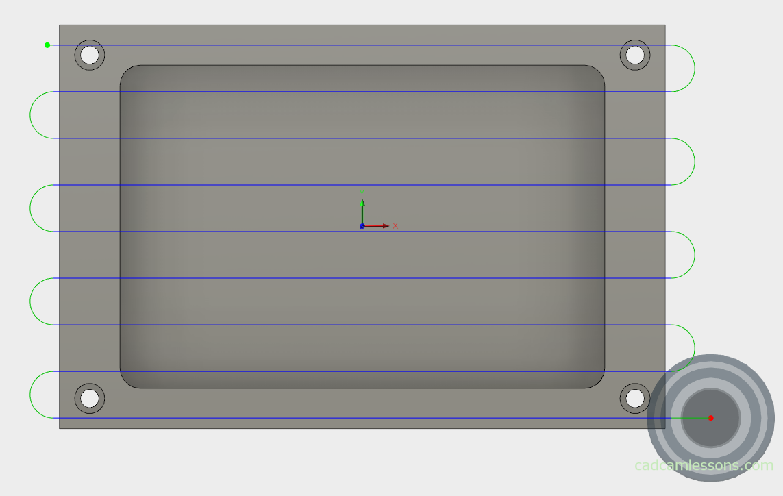
Another option is Pass Extension. The value 0 is shown below.

And in the following figure, the value of Pass Extension = 10.
We can easily see that this option is responsible for extending the passes (as the name suggests) at the beginning and end of pass.
In our example, the toolpaths were extended only from the left and right side (if there was a different angle of passes is just at the beginning and end of the pass), what if we want to further extend the machining at the top and bottom of the element? So that on each side the tool goes beyond the workpiece by a certain value? The Stock Offset option will help.
In the case when Stock Offset = 0 (and Pass Extension = 0), we get:

In the case when Stock Offset = 10 (and Pass Extension = 0), we get:

The Stock Offset option is responsible for virtual enlarging the stock (in the case of 2.5D operation) by the entered value. On CAM systems this can be specified as an additional oversize.
Stepover
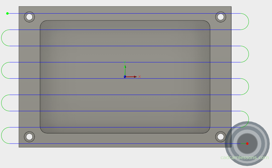
The next parameter is Stepover, which is the width of the passes. By entering a small value, e.g. 2, we’ll get:
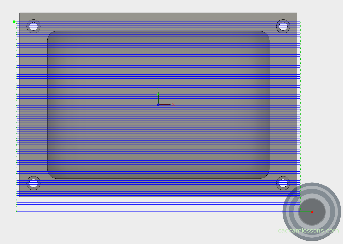
And entering, for example, 25, we will get:
You can see the difference immediately and you can see what’s going on.
The next parameter is Direction.
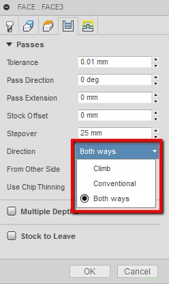
You can choose between Climb milling, Conventional milling or Both Ways.
From Other Side
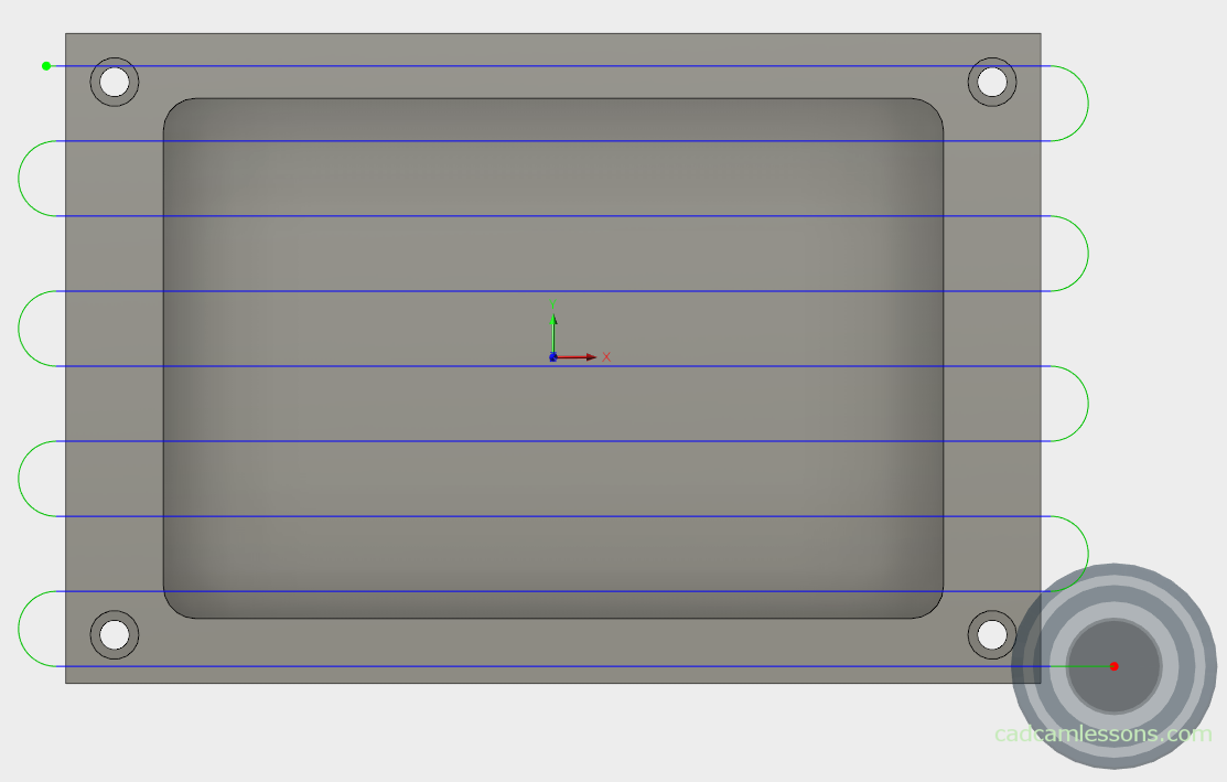
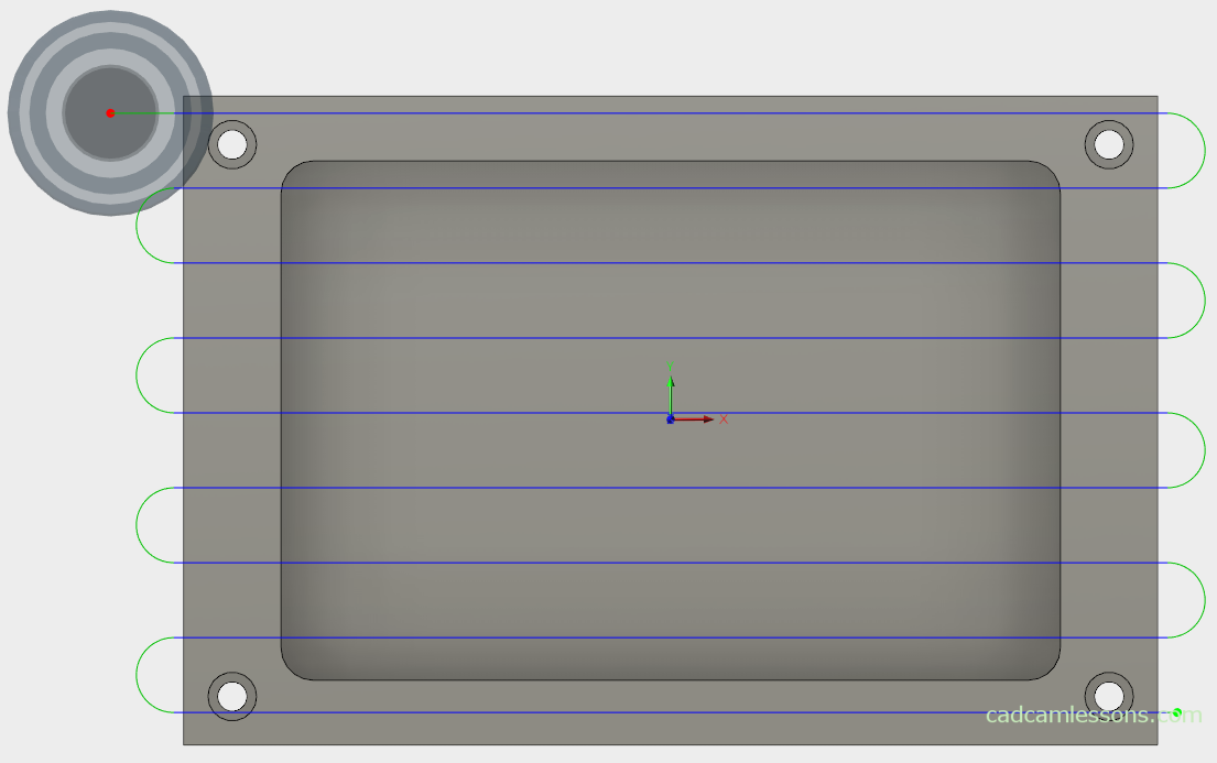
Another option is From Other Side, which means changing the start of machining. Selecting it will cause the machining to start on the other side.
The From Other Side option unchecked:
The From Other Side option is selected:
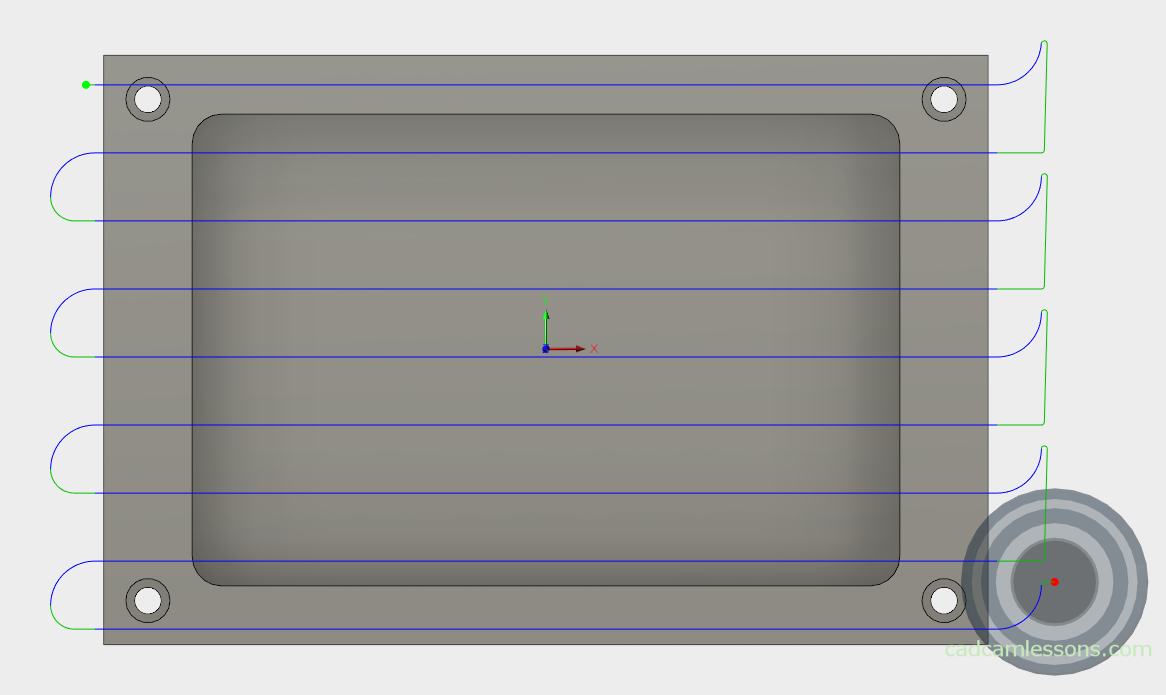
Another option is Use Chip Thinning. After selecting this option, loops will appear at the beginning of the pass.
Multiple Depths
The next section is Multiple Depths. The first parameter in this section is the Maximum Stepdown parameter. This is a quite important parameter. With it, we determine how deeply the tool will go down in one pass.
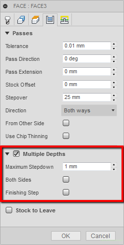
If we have 2mm of material to remove, and the Maximum Stepdown is set to 1mm, we will get two passes in Z-axis.
Both Sides
Another option is Both Sides (it will work when there will be more than one pass). If this option is not selected then the machining will proceed in one direction, i.e. from bottom to top (from negative values of Y axis to positive values of Y axis) or from left to right (from negative values of X axis to positive values of X axis) in depending on how the toolpaths have been prepared.
After machining is performed on the first step values in the Z axis (in our example on Z-1), the tool travels over the material to the opposite side and starts machining at the next level in the Z axis.
Both Sides option unchecked.
Both Sides option checked.
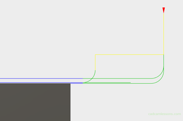
Finishing Step
Another option is Finishing Step.
After selecting this option, a finishing pass will be added and fields in which we can determine the feed rate for this transition and its step in the Z axis are activated.

After calculating the operation, we get two rough passes with a maximum depth of 1 mm and one finishing pass with a depth of 0.2 mm.
Stock to Leave
The last option in this tab is the Stock to Leave, which is the allowance to be left after machining for next operation.
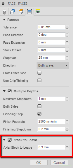
Typing, for example, 0.3 mm, we get:
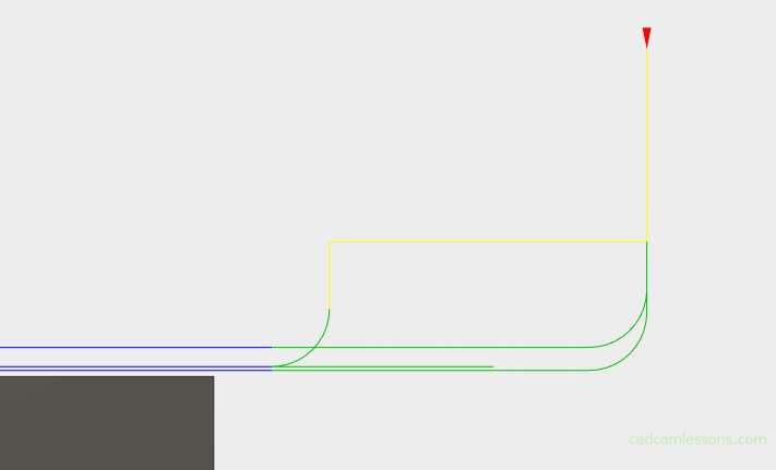
Here we have a face operation, so the allowance will be left in the Z axis. If we machined the outer contour, the allowance would remain in the XY axis. In the case of 3-axis machining, it will look different. But we will discuss it later.
Linking
The last tab is the Linking. Here, we can set the appropriate linking of passes or the approach and retract of the tool.
The first section is Linking.
High Feedrate Mode
The first option in this section is the High Feedrate Mode option. With this option, we can determine when the rapid movement is to be generated as a G0 movement and when as a G1 with a defined feedrate.
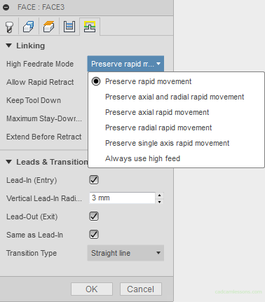
Selecting any of the parameters that converts G0 to G1 with a specified feed value will display a field in which we can determine the value of this feed.

Another option is Allow Rapid Retract. Regardless of what we set in the High Feedrate Mode, the tool retracts will be with a rapid G0.
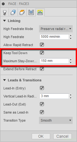
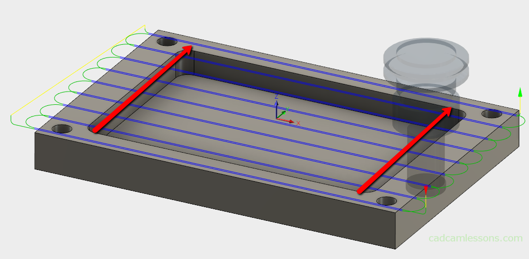
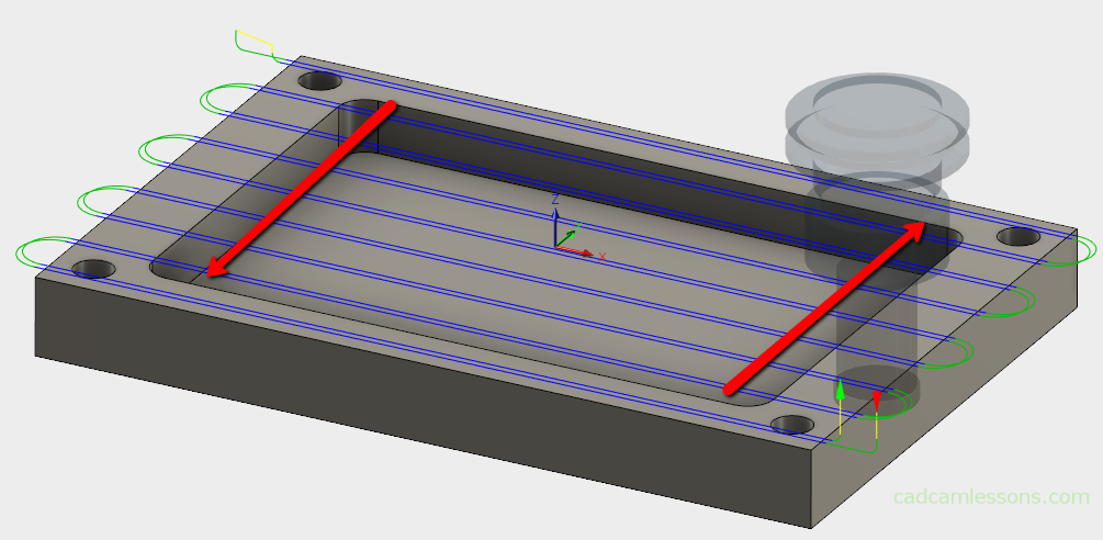
Keep Tool Down
The next option is Keep Tool Down. It is responsible for the tool not to retract during movement to the next pass, when this distance is less than that specified in the parameter Maximum Stay-Down Distance.
If, for example, a Z-2 pocket is machined, the tool after finishing one pass to the next will move to the level Z-2 if the distance is smaller than the one entered in the Maximum Stay-Down Distance field.
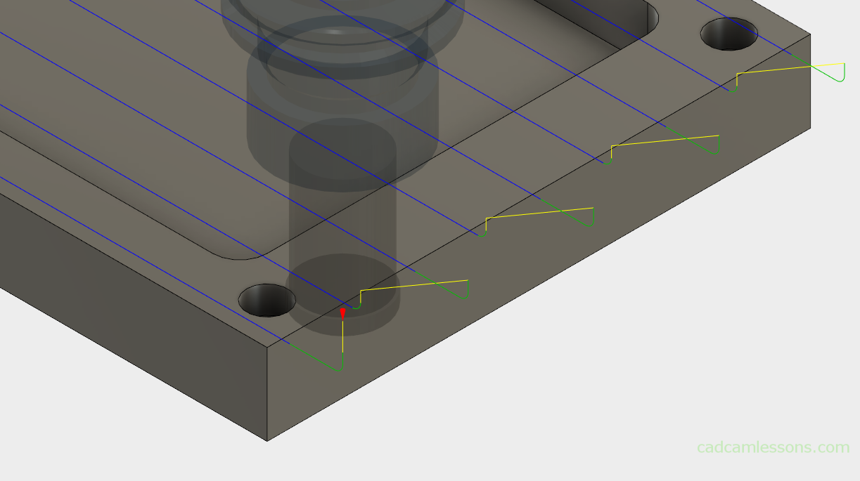
In this faceing example, it looks like this.
The Keep Tool Down option is selected:

The Keep Tool Down option unchecked:

With the Keep Tool Down option unchecked, we see the retract of tool during movements to next passes. This does not occur with the Keep Tool Down option selected. Then the tool for the next pass moves at the machining level.
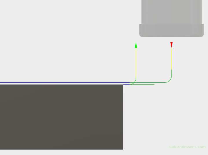
Extend Before Retract
The next option, Extend Before Retract, will cause the toolpath to be extended so that the tool will go completely out of the stock area.
The Extend Before Retract option is selected:

The Extend Before Retract option unchecked:
We can see the effect of the Extend Before Retract option in the above drawings. When this option is selected, the movement of the tool before the retract is extended so that the retraction takes place when the tool is completely out of the material.
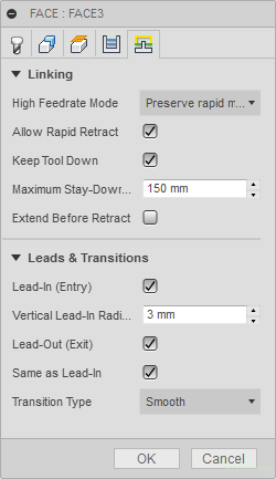
Leads & Transitions
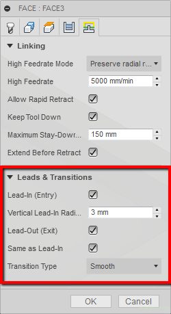
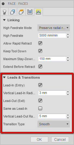
The second section in the Linking tab is Leads & Transitions. The section in which we can change the tool’s aproach into the material, its output from the material and the connection between the passes.
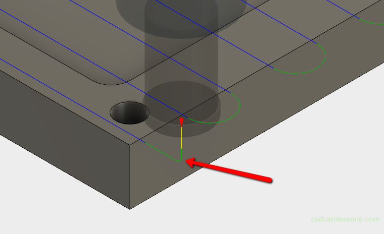
The first option is Lead-In (Entry), which is the entry of the tool and the associated Vertical Lead-In Radius parameter. By selecting this option, we will cause the tool to enter the material in an arc (vertical) with a radius whose value is specified in the Vertical Lead-In Radius parameter.
Lead-in (Entry) option selected:
The Lead-in (Entry) option unchecked:

Adding arcs in such places will cause that the machine does not change the cutting direction abruptly, only this change is smooth (in this case we have Z-axis motion and suddenly we need to change to X-axis motion). Rapid changes in the cutting direction can adversely affect the CNC machine, especially when it is a rapid motion G0. A fast moving tool in the Z axis must suddenly slow down the movement in this axis and move to the X axis. This can cause unnecessary vibrations which can shorten the life of the machine.
The Lead-Out (Exit) option, i.e. tool output from the material, works similarly, only that an arc with a defined radius will be added when the tool exits the material.
If the Same As Lead-In option is checked, the radius of the Lead-Out (Exit) parameter will be the same as for the Lead-In (Entry) parameter.
If you unselect this option, you can specify a different radius of the arc at the exit of the tool from the material.
Transition Type
The last option is Transition Type.
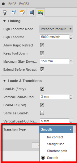
The Smooth option will smoothly link next pass.

The Shortest path option will link the next pass with the shortest path. Usually it will be a straight line (in this case after retract and leaving the material).

The Straight line option will link next pass with a straight line (in this case, after slightly exiting the tool out of the material and without retracting).

The No contact option causes that passes on the same Z level will be linked at the level of retraction distance. In this case, we get the same as using the Shortest path option.

Face strategy is already discussed. This strategy is quite often used, so we will definitely come back to it in the future.
Next strategy is the machining of contours – 2D Contour.
Face milling on YouTube!
Part 1:
Part 2:
Part 3:
If you find my tutorials helpful, you can support CADCAMLessons:
https://ko-fi.com/cadcamlessons