Heidenhain Drilling – CYCLE 203 – Universal Drilling
YouTube: https://youtu.be/frGEtOCOdRA
In this lesson we will prepare drilling operation in Heidenhain. We will use the CYCLE 203 UNIVERSAL DRILLING.
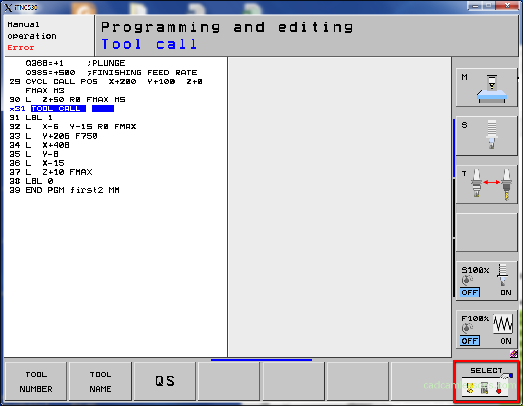
First, let’s define tool in tool table.
Press TOOL CALL button, next press SELECT softkey.
Select position 33 in the tool table and switch EDIT to ON, by pressing this softkey.
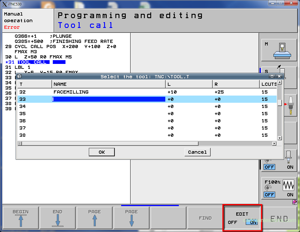
Enter name: DRILL_9, L 45 (it is 5xD), LCUTS 45.
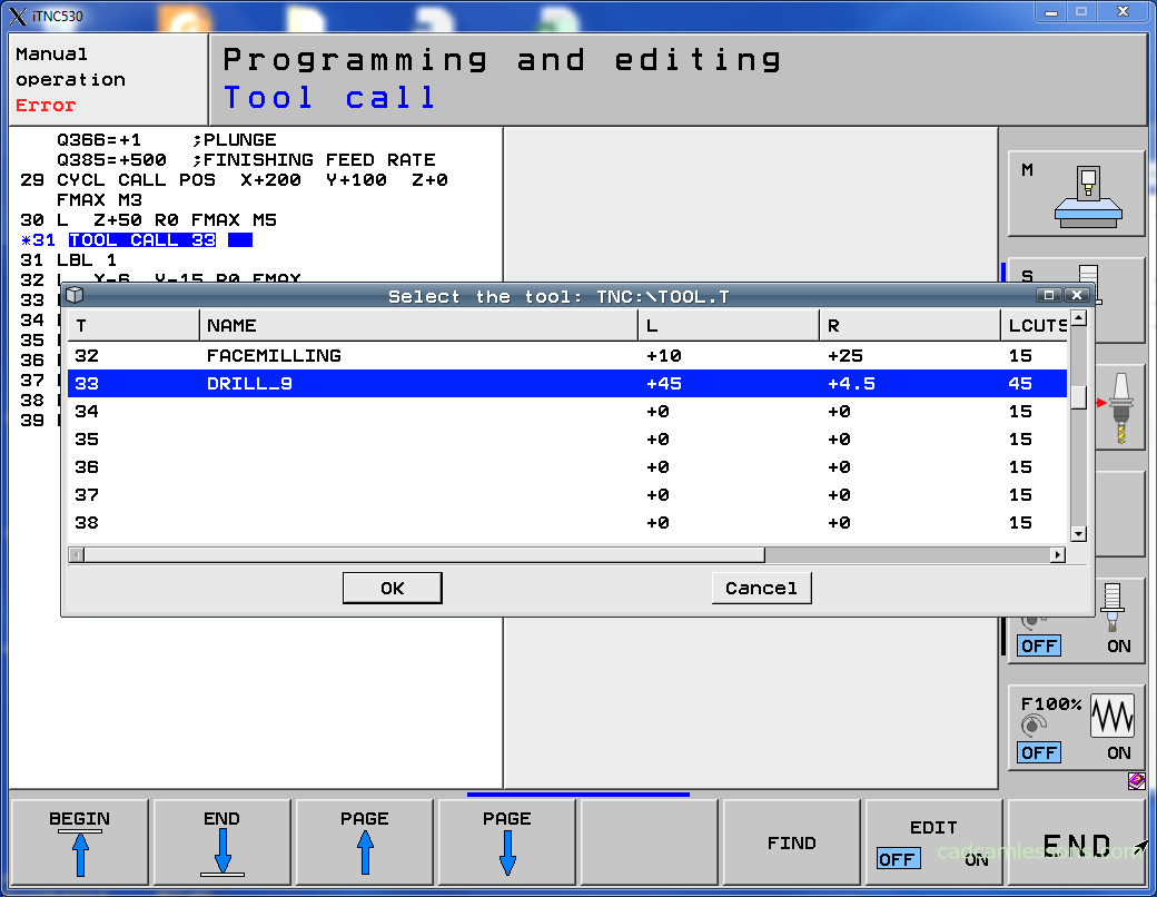
Select OK and enter Z S2000 F300.
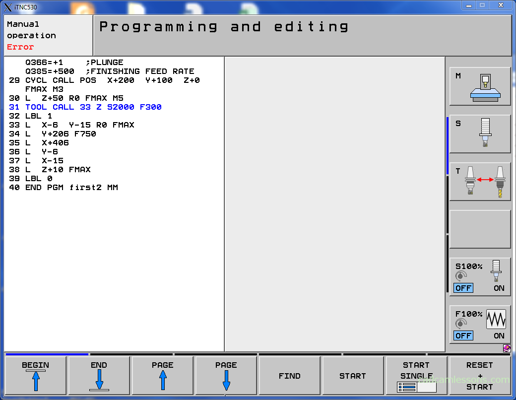
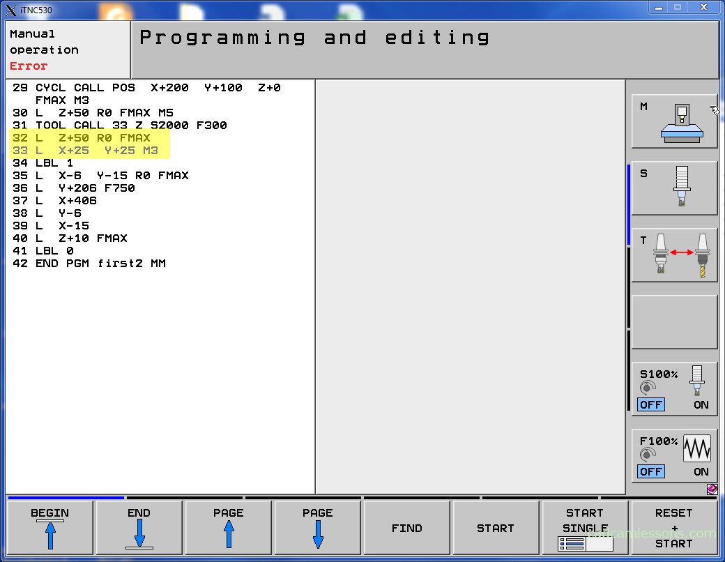
Now, let’s preposition tool. Press L and enter Z+50 R0 FMAX. And again press L and enter X+25 Y+25 M3.
Now. Let’s define the cycle. Press CYCL DEF button.

Select DRILLING/THREAD.
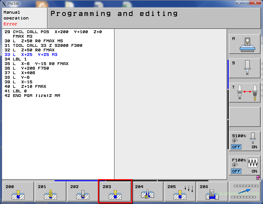
Select CYCLE 203.
First parameter is set-up clearance – Q200.
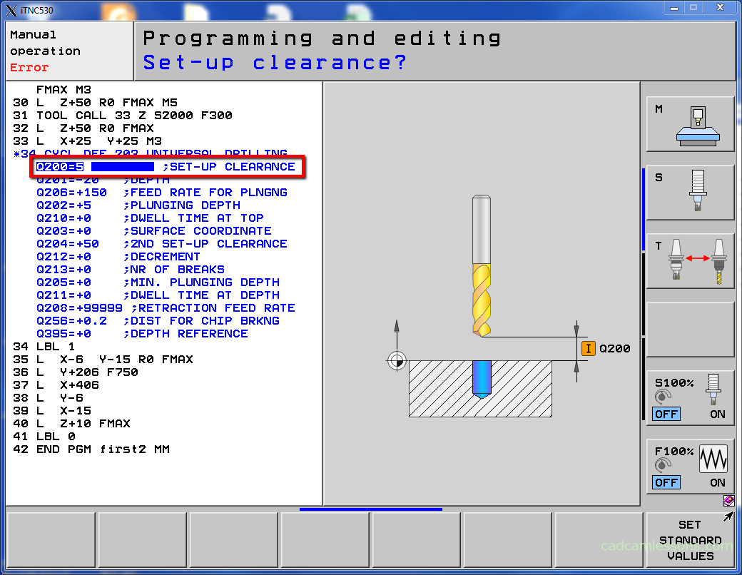
Enter 5 and press ENT button.
Next parameter is the depth.
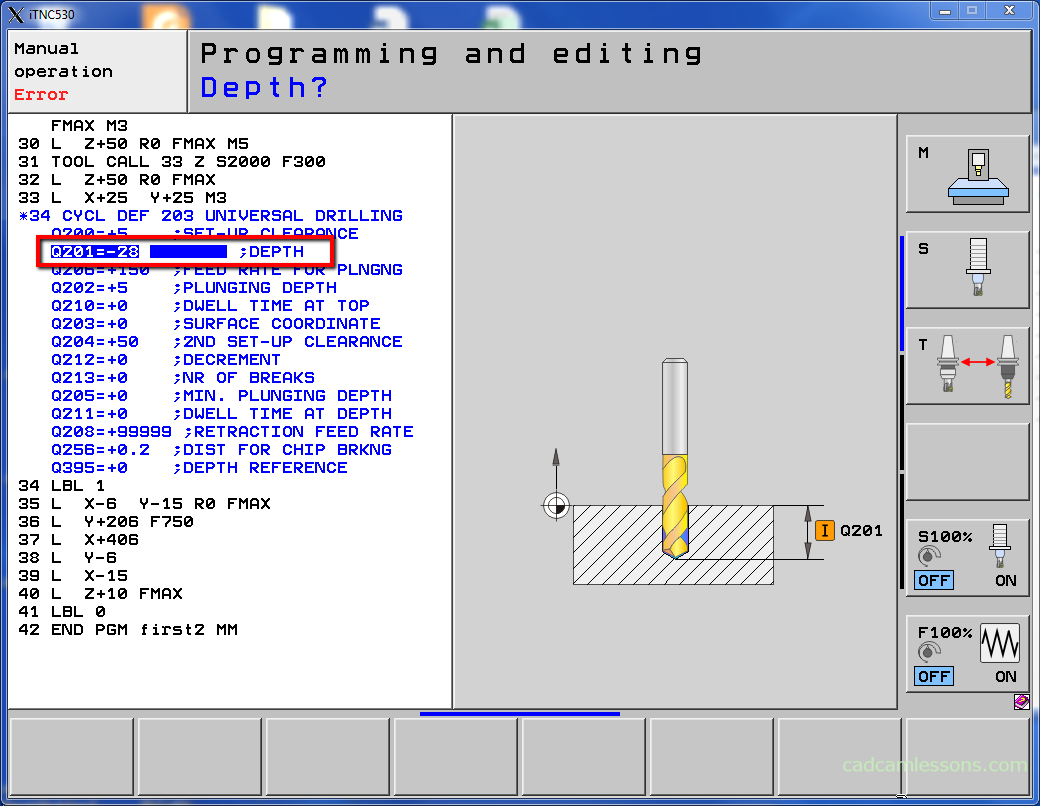
Enter -28 to make sure that it will be through hole and press ENT button.
Next parameter is the feed rate for plunging.
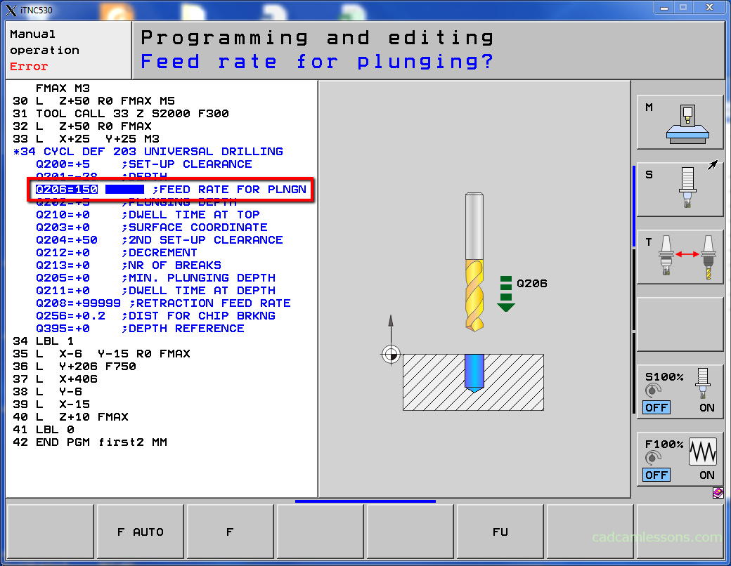
Enter 150 and press ENT button.
Next parameter is the plunging depth – Q202.
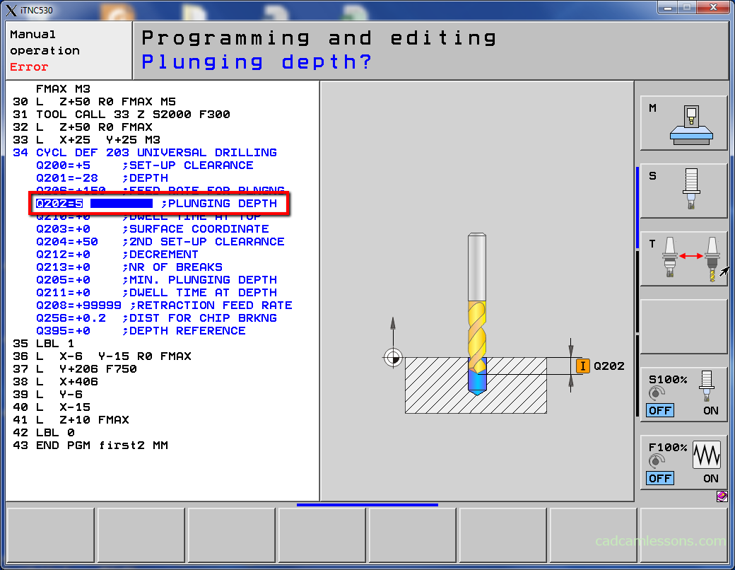
Enter 5.
The depth at which drilling will be done in a single step of the cycle. The first step is drilling at -5 and retract, next step is drilling at -10 and retract, etc.
Press ENT button.
Next parameter is the dwell time at the top – Q210.
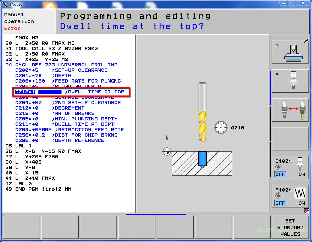
This is time in seconds in which tool is at safe height, after retract from drilled hole, for chip removal.
Enter 1 and press ENT button.
Next parameter is the workpiece surface coordinate – Q203.
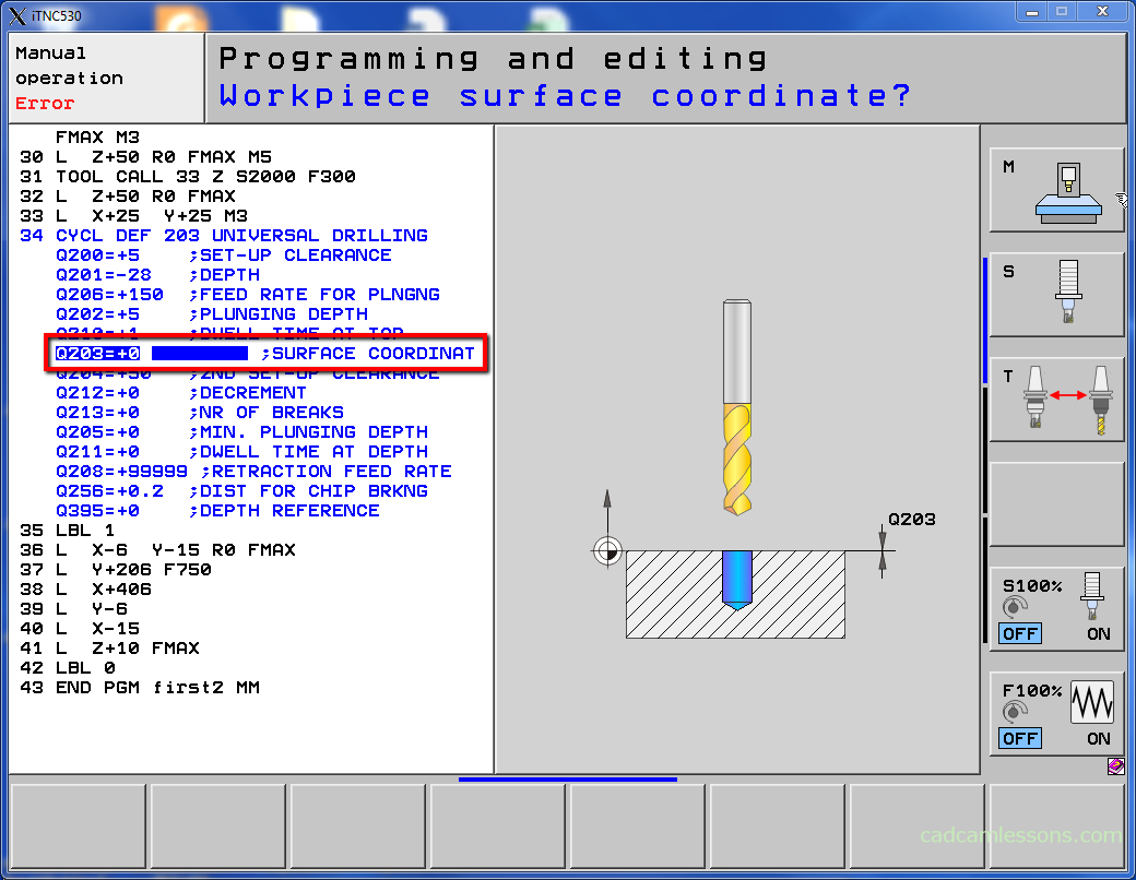
This is the Z level on which the hole starts.
Enter 0 and press ENT button.
Next parameter is the second set-up clearance – Q204.
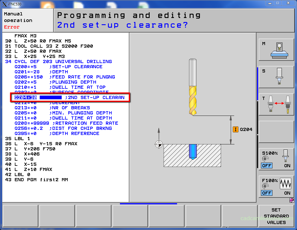
Enter 30 and press ENT button.
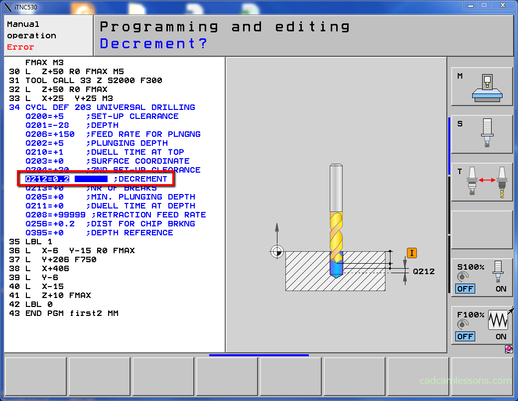
This is the value by which the depth Q202 is reduced after each step (deeper drilling, smaller depth of step).
Enter 0.2 and press ENT button.
Next parameter is the number of breaks before retracting – Q213.
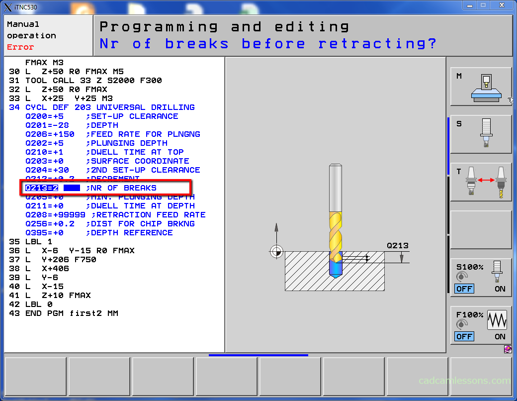
This is the number of chip breaks before tool retract from the hole for chip removal. For breaking the chip tool retracts by the value setting in Q256 parameter.
Enter 2 and press ENT button.
Next parameter is the minimum plunging depth – Q205.
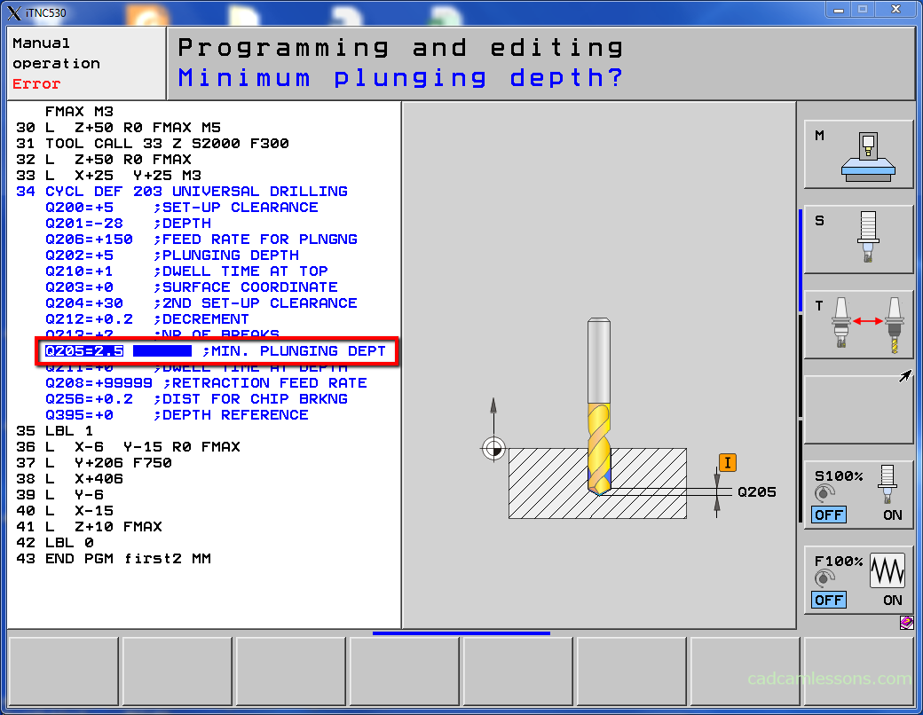
If we use the parameter Q212, then with this parameter we can determine what will be the minimum depth in one step.
Enter 2.5 and press ENT button.
Next parameter is the dwell time at the depth – Q211.

This is time in seconds that the tool is at the bottom of hole.
Enter 0.2 and press ENT button.
Next parameter is the feed rate for retraction – Q208.
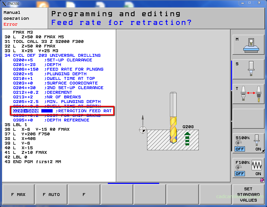
This is the feed rate for tool retract from the hole. If Q208 = 0, then tool retract will be with feed value from Q206 parameter.
Enter 5000 and press ENT button.
Next parameter is the retract distance for chip breaking – Q256.
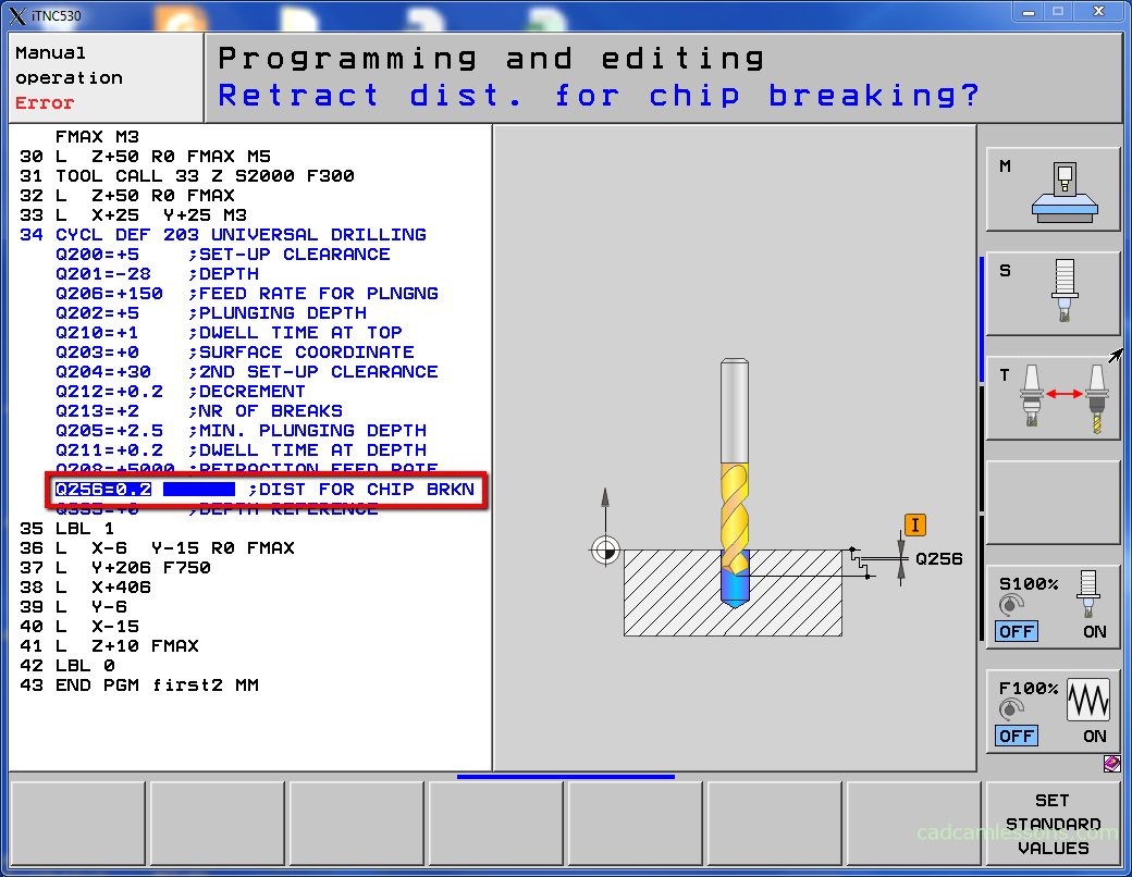
This is the value by which tool retracts when breaking the chip.
Enter 0.2 and press ENT button.
Last parameter is the depth reference – Q395.
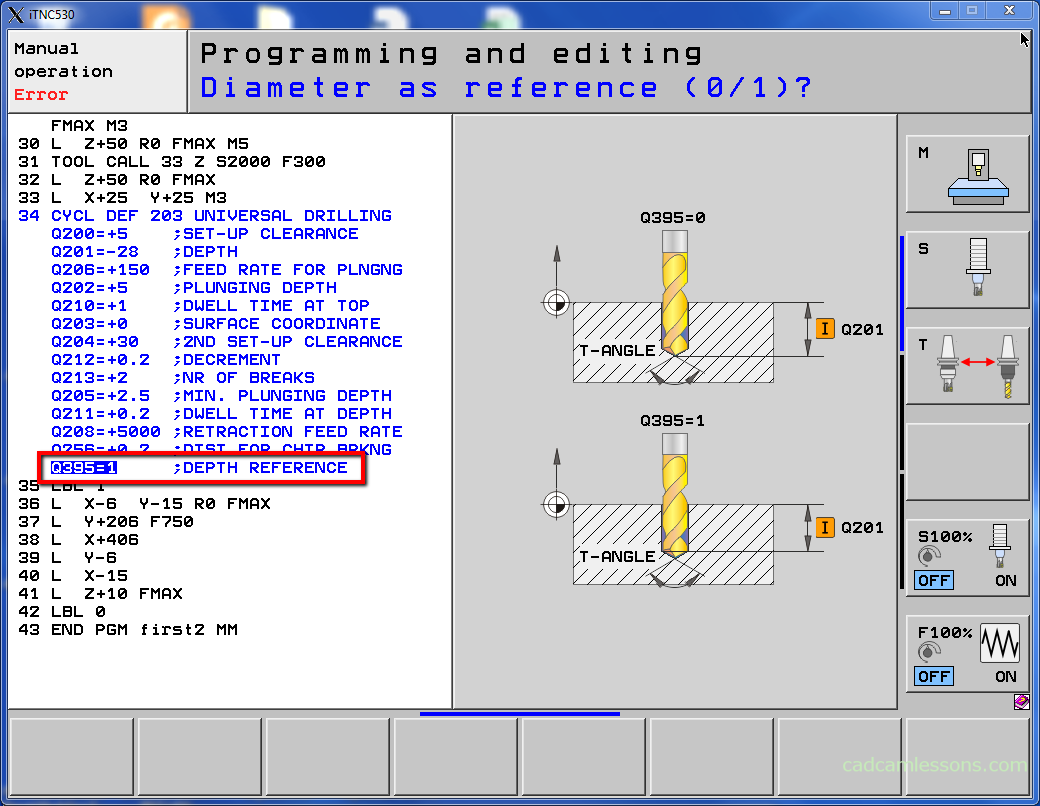
You can choose whether the depth of drilling is refer to the tool tip or to the cylindrical part of the tool. If to the tool tip you have to define tool tip angle in the tool table in the T-ANGLE column.
0 means depth refers to the tool tip.
1 means depth refers to the cylindrical part of the tool.
Enter 1 and press END button.
In the video lesson I will show you how to add tool in the tool table with T-ANGLE parameter.
Now, let’s call this cycle.
First, let’s DEL line 33 and enter X+25 Y+25 R0 FMAX M3 after cycle.
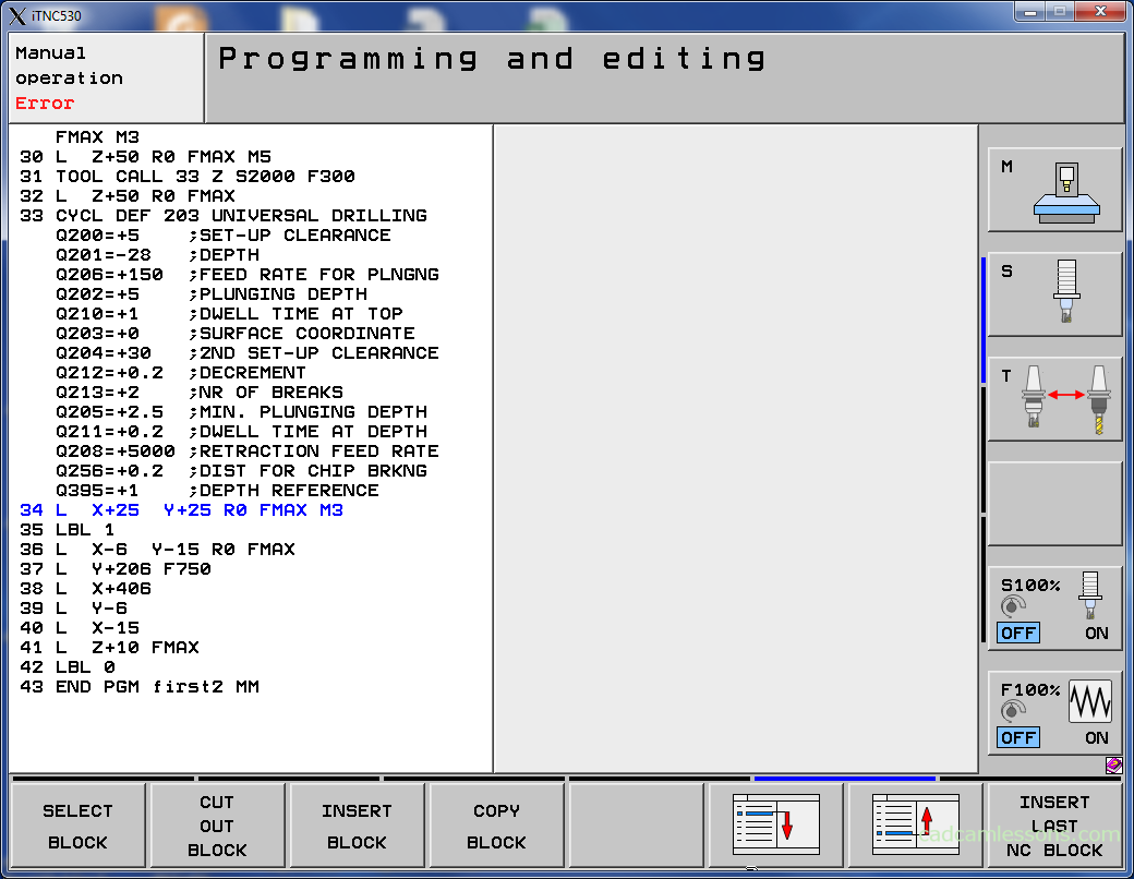
Next, press CYCL CALL button, select CYCLE CALL M and press END.
And add few lines.
Line 34: L X+25 Y+25 R0 FMAX M3 is the positioning tool for drilling first hole.
Line 35: CYCL CALL is the calling the cycle.
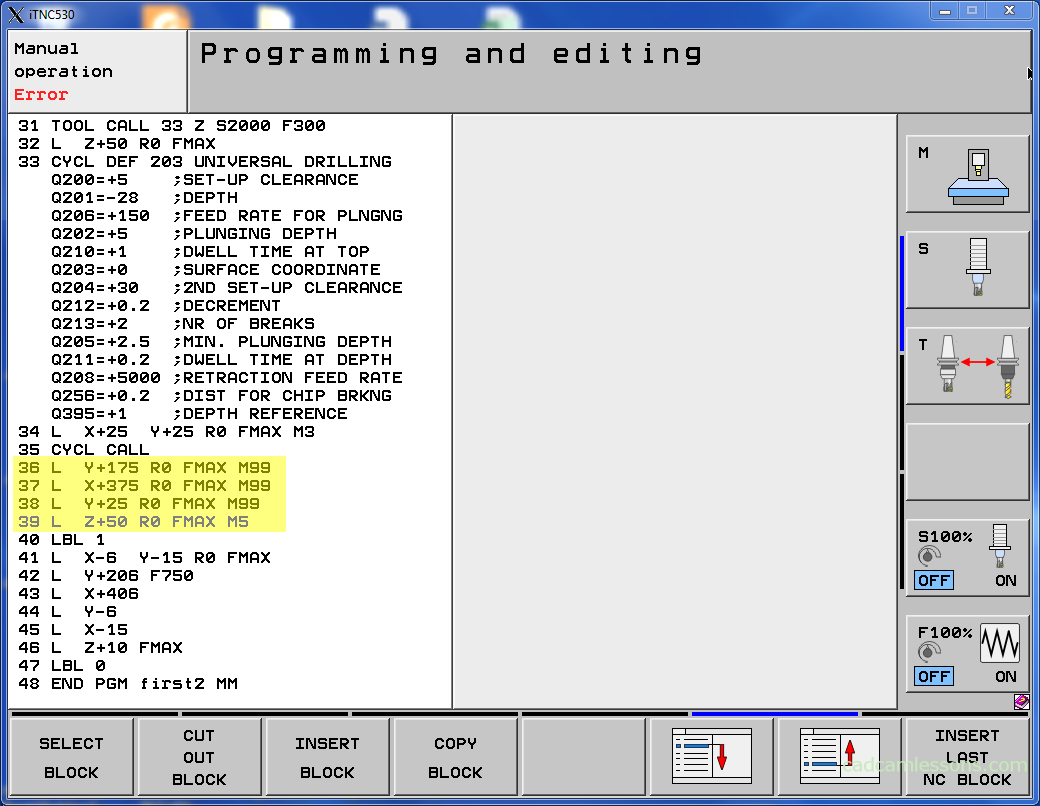
Line 36: L Y+175 R0 FMAX M99 is the positioning tool for drilling second hole and calling cycle.
Line 37: L X+375 R0 FMAX M99 is the positioning tool for drilling third hole and calling cycle.
Line 38: L Y+25 R0 FMAX M99 is the positioning tool for drilling fourth hole and calling cycle.
Line 39: L Z+50 R0 FMAX M5 is the tool retract.
Save the program and run the simulation.
This error may occurs.
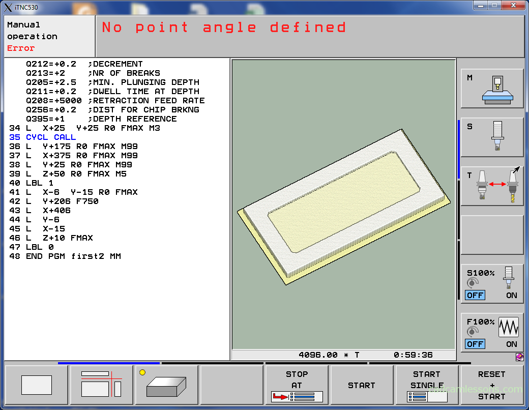
This means that we want to drill to the cylindrical part of the tool but we don’t have tool tip angle defined.
Let’s change parameter Q395 DDEPTH REFERENCE from 1 to 0.
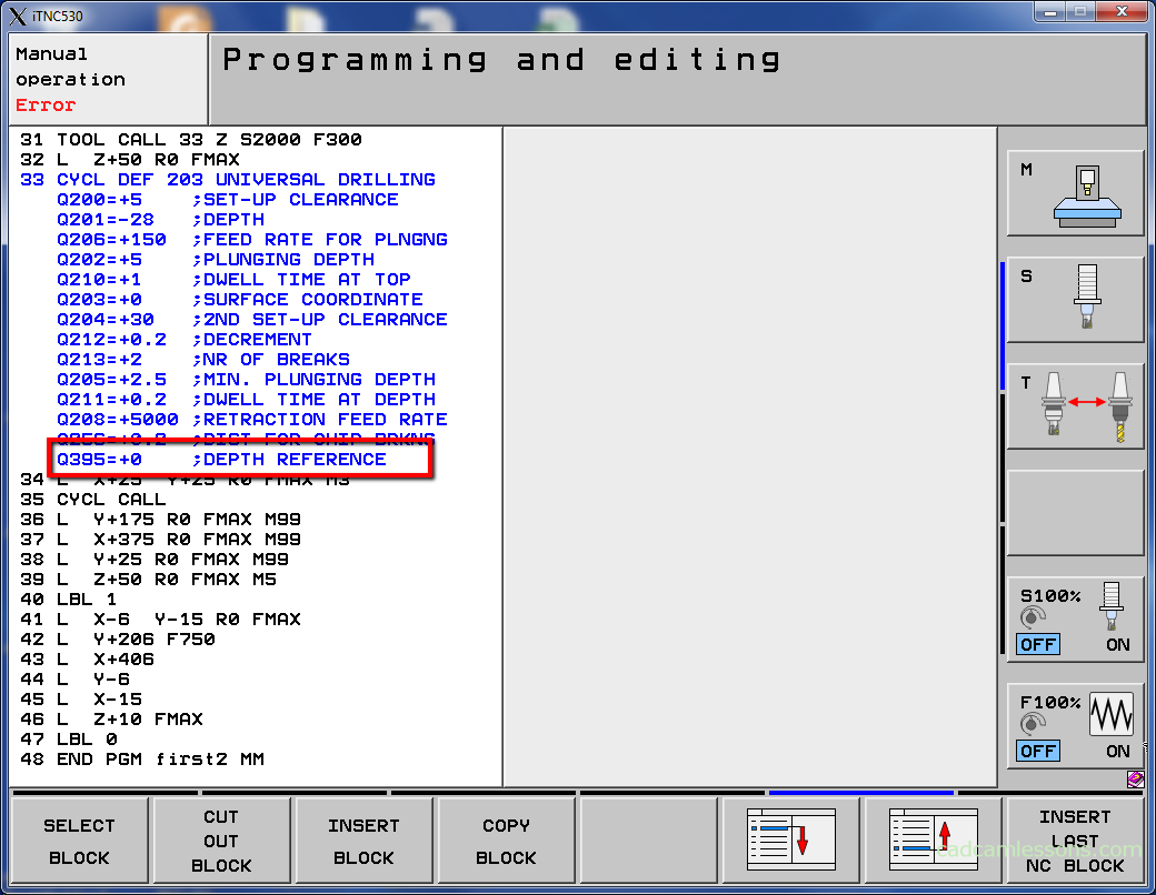
Save program and run simulation again. Now, all should be fine.

Watch the video below to get to know this drilling cycle better.
If you find my tutorials helpful, you can support CADCAMLessons:
https://ko-fi.com/cadcamlessons