
If you find my tutorials helpful, you can support CADCAMLessons:
https://ko-fi.com/cadcamlessons
Compensation and How the toolpath is generated in CAM systems?
Now, it’s worth taking a moment to understand how the tool path is generated by the CAM system. And this is not about the CAM system algorithms, but more about what is the basis for generating the tool path on the basis of which the NC program will be generated.
When machining contours, the important issue is whether we use the G41/G42 compensation or generate the code without compensation.
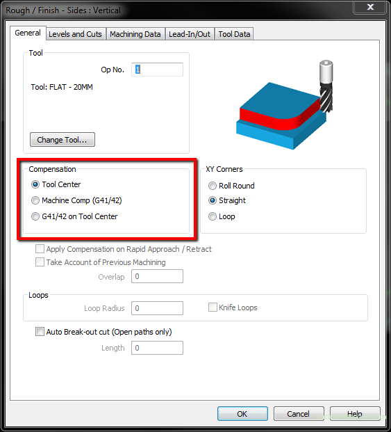
Without Machine Compensation
If you do not use tool radius compensation, the basis for generating the correct NC program is the geometry representing the workpiece and the tool that you have selected for machining (here we omit the postprocessor issues, assume that it is correct). Based on the geometry and tool diameter, the tool path is generated at the appropriate distance from the contour. In the example below, we have a square of 100 x 100 mm, a milling cutter with a diameter of 10 mm. The origin of the coordinate system is in the lower left corner of the square.

The tool path is offset 5 mm from the workpiece contour, i.e. by half the tool diameter. So we can conclude that the tool path describes the movement of the tool center point. Let’s see what it will look like in the NC code.

By analyzing the NC code, we see that the machining starts with the X-5 Y-5 coordinates. Apart from the movement in the Z axis, the tool moves to the coordinates Y105 (where X remains unchanged, i.e. X-5), then to X105 (Y unchanged, i.e. Y105), then to Y-5 (X remains at the X105 values) ), and at the end of X-5 (and Y-5), that is, we return to the starting point. Throughout the machining, the tool is moved away from the contour by 5 mm per side. The tool path describes a 110 x 110 square. The tool is already offset by half the tool diameter from the machined contour, i.e. from the nominal dimension. By running this program on a CNC machine we get a part with the correct dimensions 100 x 100 mm (in the ideal case, when the tool has a diameter of 10 mm).
With Machine Compensation
Let’s check how it will change if you apply the G41/G42 tool offset (Machine Comp (G41/G42)).

Here, similarly, machining starts with X-5 Y-5 coordinates, but then we have X0 Y100, then X100, then Y0 and finally X-5. So the center of the tool moves over a 100 x 100 mm square. By running such a program, we will receive a 90 x 90 mm part.
A tool offset would be helpful here. We even checked the right option in Alphacam before generating the machining program, but what went wrong?
In CAM systems, one of the most important issues is a properly implemented postprocessor. At this point, we use the default postprocessor installed in Alphacam, and there may be no options implemented there that are responsible for the G41/G42 compensation. That’s why we have to be careful if we use postprocessors that are not adapted to our machine (e.g. the ones we find on the internet). Such postprocessors, from an unreliable source, can do many costly damages on the machine.
Lead In/Out
But after checking the postprocessor, it turns out that the functions responsible for the tool compensation are implemented. So what’s going on?
The fact that a warning appeared during the generation of the machining program.

Of course, I ignored the warning and clicked OK. And the program is wrong. And the lack of tool in and tool out is responsible for everything. And while in the case where we do not use tool compensation, the lack of entry and exit of the tool does not bother us at all. But when you want to use the tool radius compensation, you must have the tool entry and tool exit so that there is place for turning the tool compensation on.
This is how the tool path looks like without the tool entry and tool exit. The tool will goes down vertically, like a drill, at the start of machining.

Now, let’s add the entry and exit of the tool suitable for applying the compensation. Yes, the tool entry and exit must be suitable for applying the compensation.
We will not apply compensation if the first movement of the tool is an arc. For example, as in the example below.

And the worst thing is that the CAM system will most likely not give us any warning (Alphacam does not report an error). The machining program was generated without any warning. And in the program there is no G41 function.

What will cause that no error will appear on the machine. So we will get undercuts on the part. As if the G41 code was generated here, the machine tool controller would display an error. Compensation can be applied, in most cases, when the first move is to move on the G1 line, not the arc move, G2 or G3. The controller must recalculate the tool path properly, it must be moved away by the appropriate value from the machined contour and has a problem to do if the first movement is an arc. I did not have a situation in which the CNC machine controller applies a compensation in the arc move. But I do not insist that it is impossible.
So what entry and exit of the tool will be correct and will always work? Unfortunately, this question can not be answered. The least problems occur when the entry line is clearly different from the rest of the tool path.

With the entry and tool of the tool shown in the drawing above I have the least problems if I use tool radius compensation. First, we have an entry on the line that goes into the arc and the tool gently enters the material.
Summary
After this simple example, we can say that the basis for generating a machining program is the geometry of the part, the diameter of the tool and whether we use the G41/G42 compensation. If you do not use tool radius compensation, the CAM system will automatically generate the tool path offset by half the tool diameter from the contour being machined. The problem can occur when the tool is blunt and we want to get the exact dimension. For example, a tool instead of a nominal 10 mm diameter has 9.9 mm. The program will be generated for a tool with a diameter of 10 mm, and in fact machined with a tool with a diameter of 9.9 mm. We will get a 0.1 mm allowance on the dimension. What in the case of rough tolerance will be correct (for the above example 100×100) and the part should be accepted. And there is no need to use tool compensation to improve this.
However, if we need to get a dimension in narrow tolerance, it may not work to get it right after the first run of the program. Then it is worth applying the G41/G42 tool compensation and adjust the tool path directly on the machine.
Since the compensation allows you to adjust the program directly in the machine, why not use it all the time? I have several reasons, among other things, that sometimes there are problems with the program in which the compensation occurs. Another thing is that the CNC operator may not reset the compensation values from the previous program in the tool table in the machine and then the program will go straight away with the previously entered compensation value – and it is not known what was entered. So I have a simple rule, if I do not need to use tool radius compensation, I do not use it.