Minimum Cutting Radius
YouTube: https://youtu.be/WpTVMsKlC7E
During machining, often at the beginning of the process, we first use tools with a larger diameter to quickly and efficiently remove a large amount of material, and then go to tools with smaller diameters to properly finish the workpiece.
When processing pockets or internal contours, their inner radius is much smaller than the radius of the tool, which results in sharp corners in the toolpaths. This is not good for the tool or the CNC machine. In the sharp corners of the tool path, the tool is more loaded and wears faster. There is also a rapid change in the cutting direction. The machine must stop in one direction to move to the other direction.
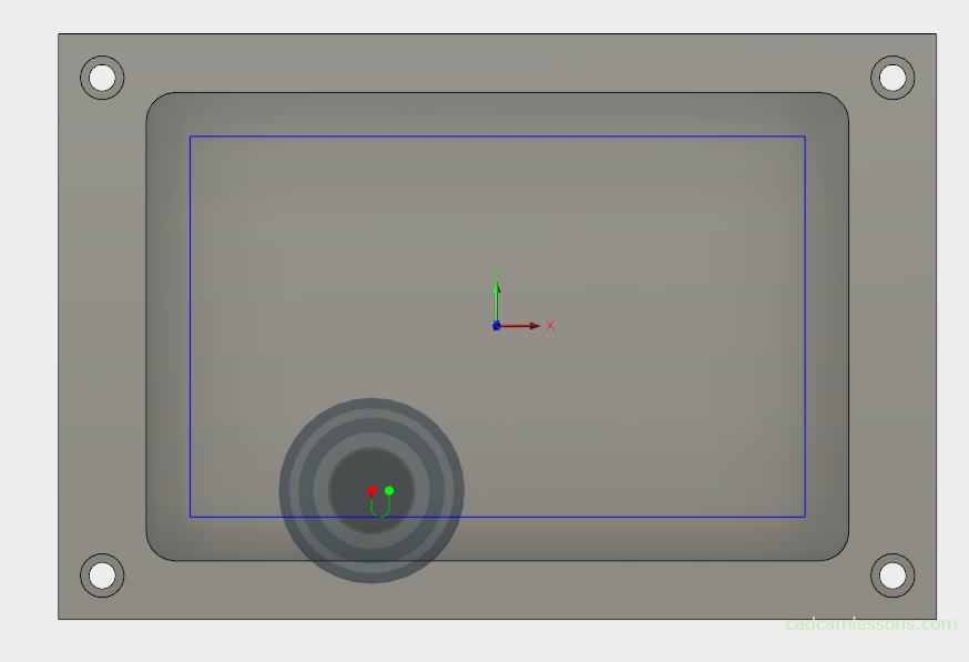
How to deal with this?
We can manually modify the geometry and add larger radii in the corners than the tool radius, but this approach is time-consuming and there may be some errors.
Another way is to use the Minimum Cutting Radius option.
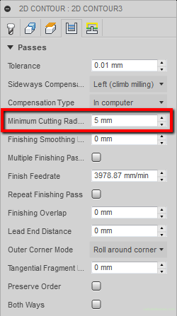
We can specify here what minimal radius should remain on the tool path. The value entered must be less than the radius of the tool that we will be working on this geometry.
After calculating the tool path, we get:
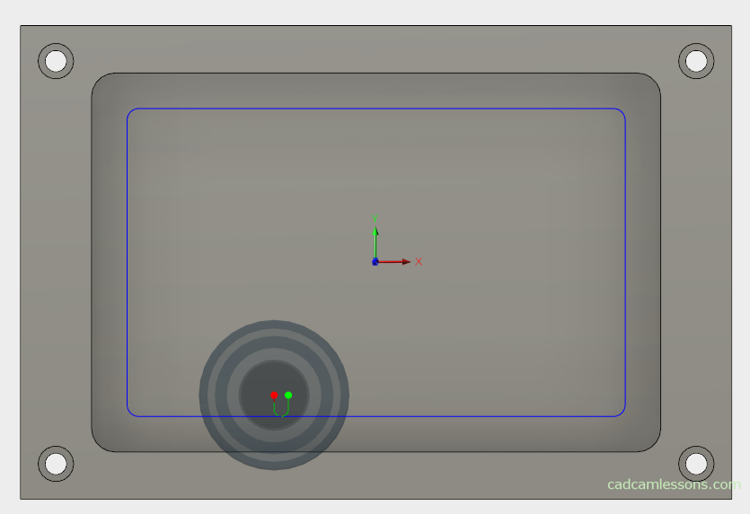
We see clearly roundings in the tool path. Of course, we must remember that the more value we enter, the more material will remain in the corners.
If you find my tutorials helpful, you can support CADCAMLessons:
https://ko-fi.com/cadcamlessons