Compensation Type – Cutter Radius Compensation – Fusion 360 2D Contour
YouTube: https://youtu.be/LVmuSM–zIY
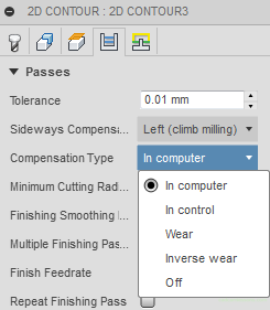
Another important parameter is the Compensation Type, which means Cutter Radius Compensation. We have several options here to choose from.
Before we discuss the above options and what is the compensation of the tool radius, let us explain the question of the basis on which the toolpath (and machining program) is generated.
When we prepare a machining program, we define exactly how this point will move. If you want to machine e.g. a 100 x 100 mm cube, this point will move on a square with side 100 + the radius of the tool (e.g. in the case of a 12 mm milling cutter it will be 106 x 106 mm square).
It rarely happens that the cutter 12 has diameters equal to 12 mm. There are usually some inaccuracies in the dimensions of the tool. And in addition, during machining, the tool is worn out, which causes its diameter to decrease. What’s more, the tools are sometimes sharpened and often come back from sharpening with different diameter. For example, two tools with an initial diameter of 12 mm can come back from sharpening with diameters 11.9 and 11.95.
What will happen then and how to deal with it? Let’s check and discuss next options of tool radius compensation.
Cutter Radius Compensation Off
In computer – selecting this option, compensation will be calculated when generating the tool path for the selected tool diameter. By selecting a tool with a diameter of 12 mm, the tool path is offset 6 mm from the machined contour. G41/G42 codes will not be generated.
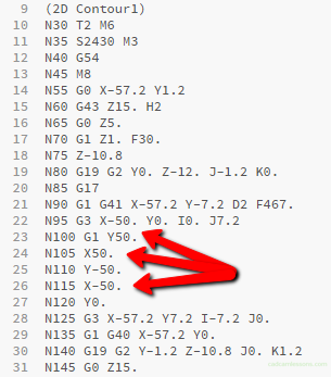
In the example, we machine a square 100 x 100 mm. The origin of the XY coordinate system in the center of the cube.

We see that the machining proceeds in X56 and Y56 coordinates, i.e. the tool is moved 6 mm away from the machined contour and moves to the left of the contour, which we have determined by selecting the machining side. There are no G41 / G42 codes responsible for turning on the tool radius compensation.
In this case, when we use a tool with a different diameter than the one used in the CAM system, we get the material undercut or leave the finishing allowance. Here we use a 12 mm cutter. Let’s assume that the tool will actually have a diameter of 11.9 mm. The tool path will still be offset by 6 mm from the contour, so we will get a 0.1 mm allowance.
In the case when we use a smaller tool, we can easily improve the detail and remove the allowance, and when the dimension is in the workshop tolerance, it will be acceptable.
What when instead of a 12 mm cutter we will use a 16 mm cutter?
Then we have a problem. Because the tool path is only moved 6 mm away from the contour all the time, and the tool radius is 8 mm … We will get a detail 4 mm smaller than it should be.
Let’s check how the tool correction works and what its advantages are.
Cutter Radius Compensation On
In control – selecting this option the cutter radius compensation will be applied by reading data from the machine controller’s tool table. The G41 / G42 code will be generated, and the NC code will represent the toolpath as if the tool moved with its center along the contour. It will not be moved in any direction from the contour. It is only in the machine controller that it will be offset by the actual tool radius value.
At first glance, we see that the tool moves along the contour with its center. CNC beginner programmers can worry, but there is nothing to be afraid of. The program is valid thanks to the G41 code, which causes the actual tool radius value to be read from the tool table and the toolpath is moved to the left of the contour by this value.
Let’s return to the examples from previous option, when we didn’t use the cutter radius compensation. In the case of a tool smaller or larger than tool used during programming, we get an allowance or undercut.
Now, when we use the cutter radius compensation and, for example, we use a tool with a diameter of 11.9 mm (and this diameter will be entered in the machine controller), the tool path will be offset by 5.95 mm from the programmed contour and we get the nominal dimension that we want to achieve.
Using a 16 mm milling cutter, the tool path will be offset 8 mm from the programmed contour and, the same, we will get the nominal dimension.
In summary, the In computer option means that the cutter radius compensation will not be enabled. The In control option means that the cutter radius compensation will be on.
If you find my tutorials helpful, you can support CADCAMLessons:
https://ko-fi.com/cadcamlessons