
Tool Directions – Ghost Tools
YouTube: https://youtu.be/0tqN1QMuFw4
At this moment, our drawing consists of several individual geometries. If we would like to machine, for example, an external shape, it would be difficult because we do not really have a geometry that completely represents the outer contour of the part. But how do you check it?
One way we got to know in previous posts, it was to use the Delete option to check if the geometry is single. But this is not a typical way to check whether geometry is a single geometry or composed of several smaller ones. Another way is to use the Ghost Tools option.
Choose View | Display Options | Ghost Tools or use the keyboard shortcut Ctrl + G.

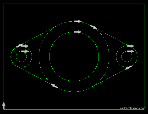
White arrows appeared in the drawing. Each arrow means a single geometry. It also means the direction and side of machining.
Choose Machine | Tool Directions. The following window will appear.
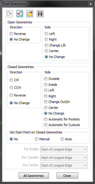
As you can see, we have two types of geometry. Open geometries and closed geometries. Open geometries are geometries whose begin and end lie at a different point, on our example drawing these are lines. Closed geometries are geometries whose begin and end are at the same point, on our drawings these are circles and rectangles.
For each type of geometry, we can specify the Direction and Side of machining. We will discuss these options on the example of an external rectangle. This is closed geometry and we will use the options in the Closed geometries section. For closed geometries we have more options, and the options we have for open geometries are very similar and their effect is practically the same.
As for the direction, we can determine the clockwise cutting direction – CW, counter clockwise CCW, Reverse to what is currently set or leave with No Change. Select the No change option when you only want to change the machining side.
At this moment, the arrow of the cutting direction of the rectangle is directed to the right, counter-clockwise. Suppose you want to receive climb milling. Therefore, we have to change the direction of processing to CW – clockwise. Select this option in the Direction section for closed geometries and without closing the Tool Directions window, click on the rectangle.
The arrow has changed its direction, but it still “lies” on the geometry. If the arrow is centrally on the geometry, it means that the tool center will move along the geometry. If the rectangle represents the size of the part then in this case (where the arrow lies centrally on the geometry) we get an undercut equal to the diameter of the tool (tool radius per side = diameter on the dimension).
To change this from the Side section for closed geometry, select the Outside option and click on the rectangle. Now the arrow will be outside the geometry and it means that the entire diameter of the tool will also be outside the rectangle and there will be no undercutting of the material in this case.

If you find my tutorials helpful, you can support CADCAMLessons:
https://ko-fi.com/cadcamlessons