Fusion 360 Tabs – 2D Contour
YouTube: https://youtu.be/f9pdG7reuTU
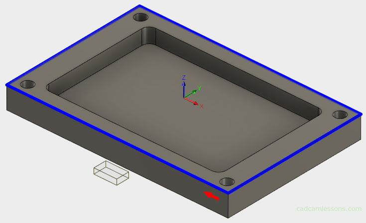
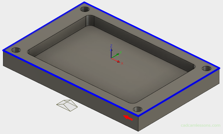
The next section in the Geometry tab is the Tabs section. We have the option of inserting automatic technological tabs.

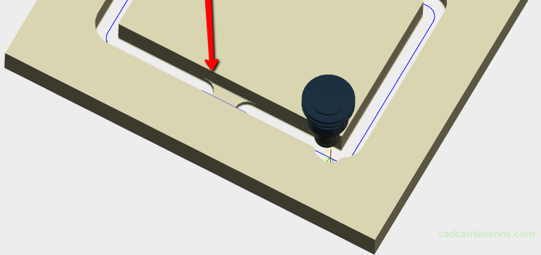
What is tabs? So far, I have often met with tabs in the machining of wood-based materials (MDF) on routers or in the machining of sheets on laser, plasma, water-jest machines. The tab holds the part to the stock. We leave a short and thin piece of material so that the part does not move when we cut it out of a much larger material or when we simply have a problem with fixing (e.g. milling thin sheets). Then we break or we cut the part from stock manually.
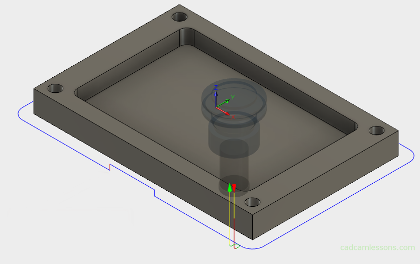
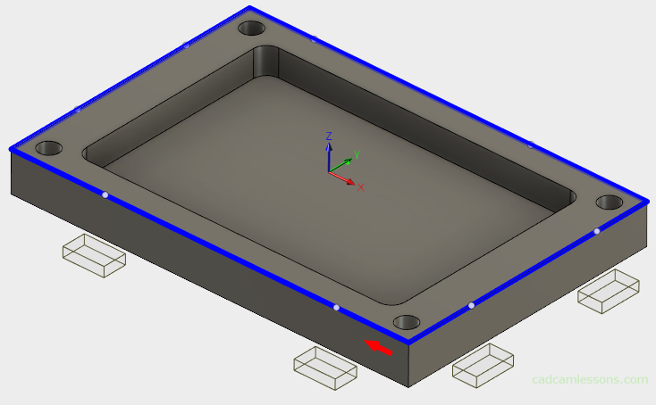
In the above figure we can see that in some parts of the toolpath we have milling a bit higher than on the rest of the toolpath. The tool goes up a little in these places, leaving a thin layer of material.
And this is how it looks after a solid simulation.
We can control the shape and size of Tabs using the available parameters.
The first one is Tab Shape.

We have two Tab shapes to choose from. Rectangular or Triangular.
Rectangular Tabs
Triangular Tabs
W can specify Tab Width and Tab Height.
The Tab Positioning parameter corresponds to the position of the tabs. We can define the position in two ways.
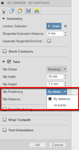
Using the By distance option, in the Tab Distance parameter we specify the distance between successive tabs. The smaller the value, the more tabs.
Using the At points option, on the model we indicate the places where we want to place tabs.
In the next post we will discuss Rest Machining.
If you find my tutorials helpful, you can support CADCAMLessons:
https://ko-fi.com/cadcamlessons