Fusion 360 Rest Machining
YouTube: https://youtu.be/Tz0wIXt6-jw
Another option is Rest Machining.
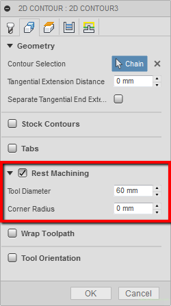
Rest machining often speeds up the machining of a part. We are able to generate the tool path only where the previous tool has left an allowance, without having to “air cutting”.
In the Tool Diameter parameter, enter the diameter of the previous tool, and in the Corner Radius parameter, the radius of its corner.
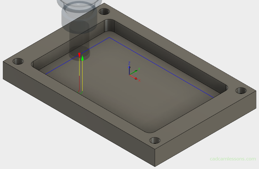
In the figure above, the tool path without the use of rest machining.
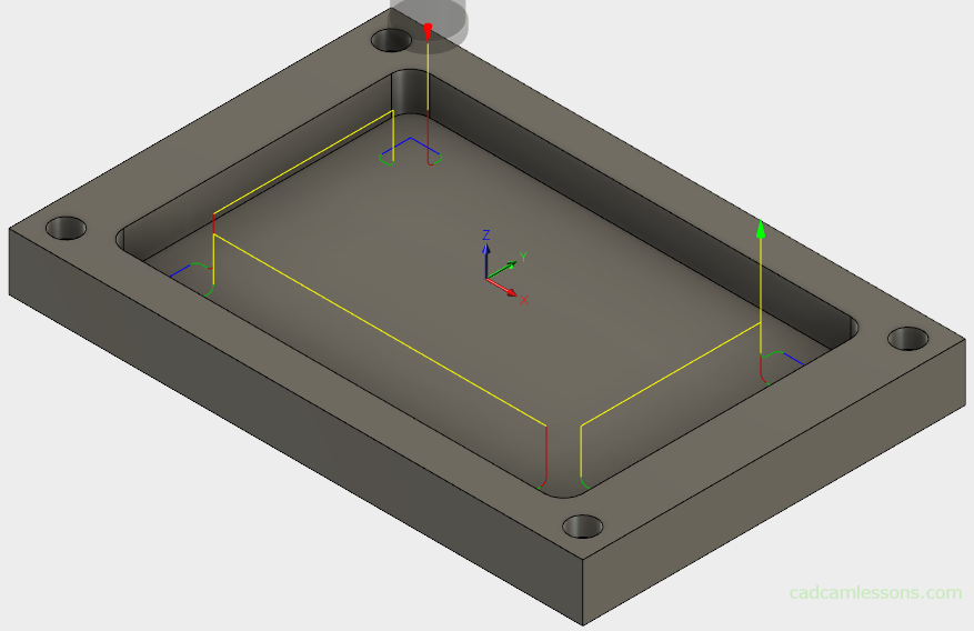
In the above drawing, the tool path using rest machining. The machining only occurs in the corners where the previous tool has left the material.
Is it worth to use Rest Machining?
It may seem that this strategy has only advantages, but is it really so?
In practice, the situation is not always ideal as in CAM systems. Why?
We have to use several different tools to machine one contour. It may turn out that the tools will be incorrectly measured, it will be visible on the part after machining. The tool we are machining, can actually have a different diameter than the one entered in the tool table (e.g. as a result of dulling). If the tool to machine the rests is not blunted to the same way, the differences can be seen on the part walls. That is why rest machining does not always make sense in practice. Sometimes it is better to machine the entire contour with a smaller tool (which is also not always good, for example the repulsion of the tool when milling at a great depth).
Of course, you have to approach this individually. If you know the machine and tools and know that everything is measured correctly, use the facilities provided by CAM systems and save time. But check the part after machining to assess whether everything went well.
The last two sections, Wrap Toolpath and Tool Orientation, apply to multi-axis machining, which we will discuss later.
Heights Tab
We know the Heights tab from previous post about Face strategy. Let’s change only the Bottom Height (the depth of milling).
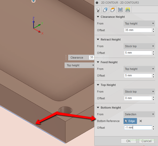
From parameter set to Selection. Select the bottom edge of the model and enter -1 in the Offset field to receive milling 1 mm below the bottom contour of the part.
If you find my tutorials helpful, you can support CADCAMLessons:
https://ko-fi.com/cadcamlessons