If you find my tutorials helpful, you can support CADCAMLessons:
https://ko-fi.com/cadcamlessons
Leads & Transitions Fusion 360
Another section in the Linking tab is the Leads & Transitions. Section for tool entry ant tool exit.
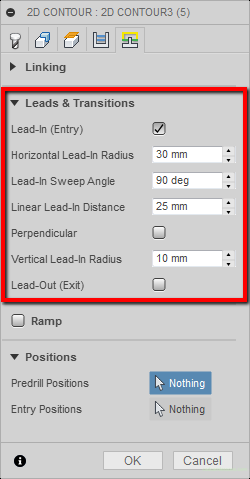
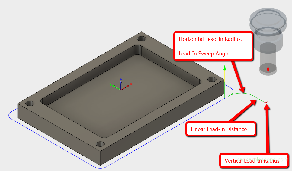
To apply a specific tool entry to the material, we need to select the Lead-In (Entry) option. After marking it, we can specify the radius of the horizontal arc (Horizontal Lead-In Radius), the angle of the arc (Lead-In Sweep Angle), the distance of the linear input between the arc in the vertical and the horizontal arc (Linear Lead-In Distance) and radius vertical arc (Vertical Lead-In Radius).
Another option is Perpendicular.
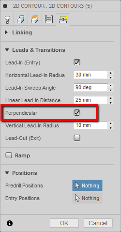
After marking it, we will get a linear extension (Linear Lead-In) perpendicular to the horizontal arc (Horizontal Lead-In Radius).
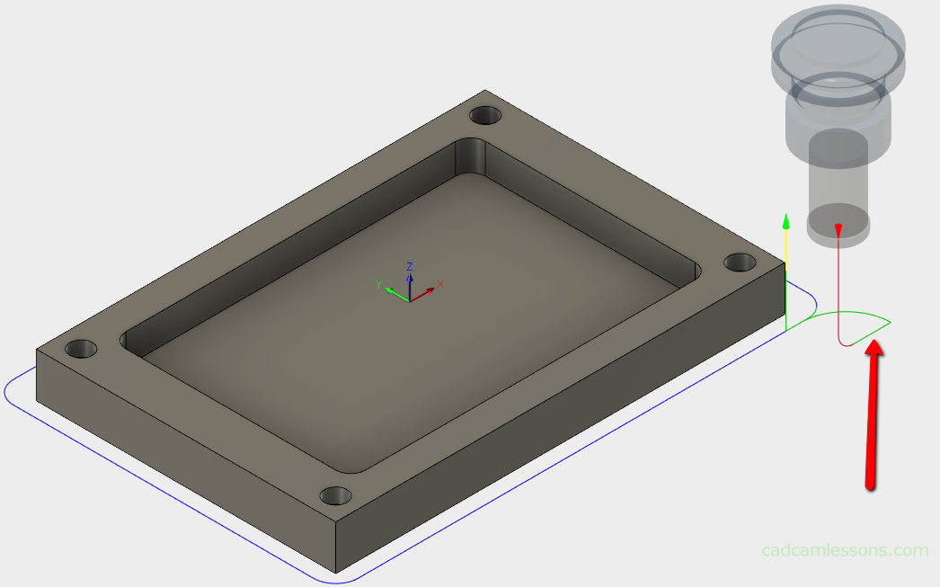
The Lead-Out (Exit) option corresponds to the exit of the tool from material.
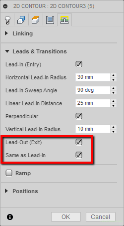
If we select this option, we can use the exit of the tool with the same parameters as the entry. Then you need to check the Same as Lead-In option.
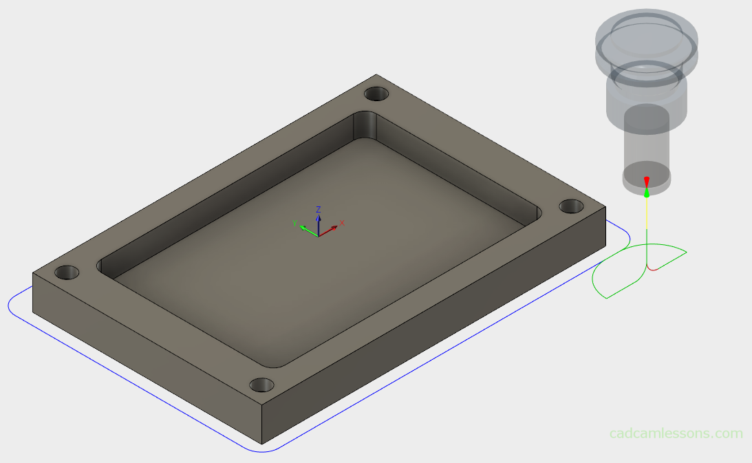
We can also deselect the Same as Lead-In option and use other parameters for the exit of the tool.
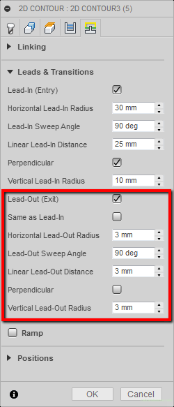
Then the tool path will look like this.
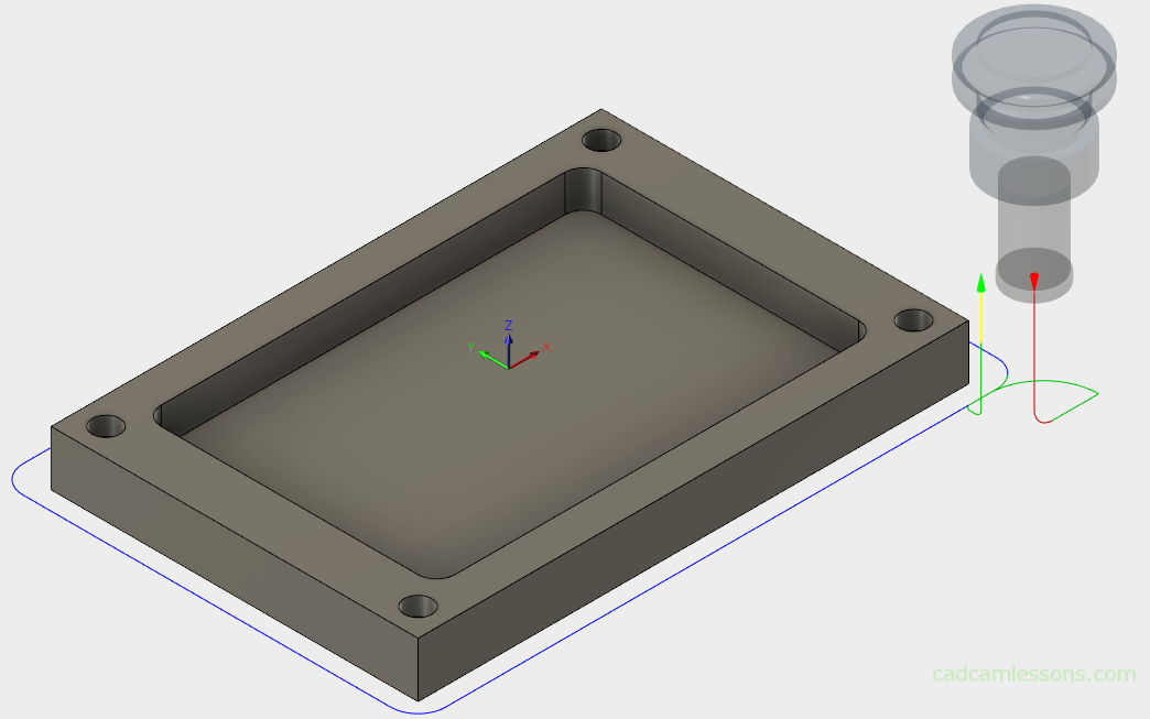
Information for novice programmers. When applying a tool radius compensation, you should always use a tool in, and the machines have a problem with applying compensation when the first move in the XY plane is an arc, so give a piece of the line where the compensation can be recalculated (in this case the compensation would be calculated on the Linear Lead- In Distance).
Using the Ramp section we can use the diagonally tool entry.
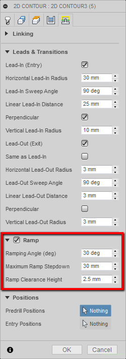
Where Ramping Angle (deg) is the angle of entry.
Maximum Ramp Stepdown is the maximum depth of a step down in a diagonal pass.
Ramp Clearance Height is the height from which the entrance will be initiated diagonally.
This is how it will look for the above parameters.

And this is how it looks in the side view.

The parameters of Ramping Angle (deg) and Ramp Clearance Height are rather clear. But the Maximum Ramp Stepdown parameter may initially cause little embarrassment.
It is best to check the behavior of the tool path for different values of this parameter. Let’s change this parameter, for example, to 15 mm.
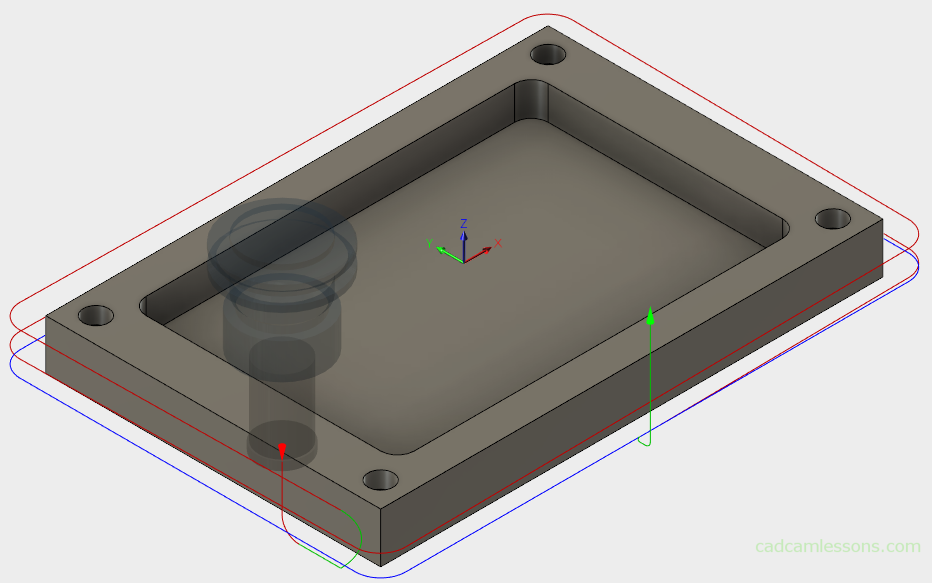
You can see that the slant entry is much longer and before the tool reaches the final depth, it moves almost twice around the workpiece contour. I remind you that the part has a thickness of 30 mm.
Let’s check now what happens as the Maximum Ramp Stepdown parameter will be 5 mm.
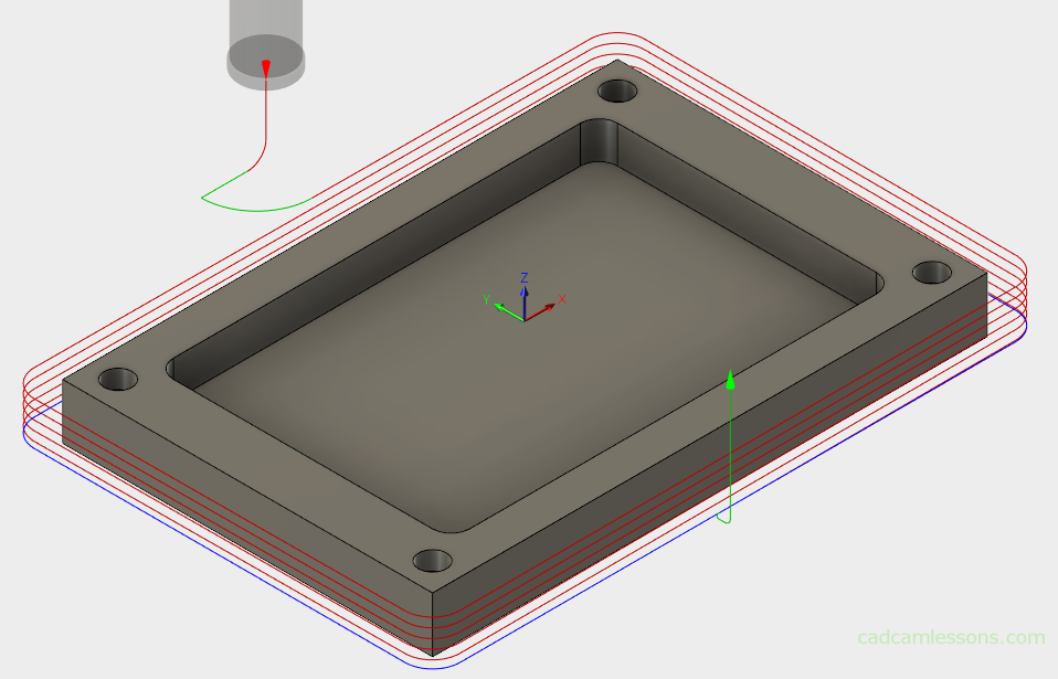
The tool moves around the contour 6 times before reaching the final depth. All this machining will be carried out with feed from the Ramp Feedrate field.
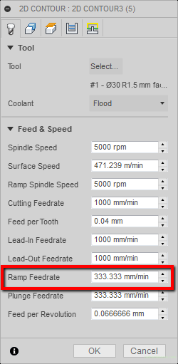
So in a very easy way we can prepare a machining known as helical machining or spiral machining. This is an interesting method of machining that causes the tool to be gradually loaded. The tool gradually sinks until it reaches the depth of the first step. The last pass will now be done as 2.5D machining at depth of the last pass.
The options from the Positions section will allow us to determine the entry point of the tool in the material.
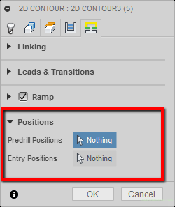
It can be a pre-hole, previously made – Predrill Positions, or any point on the contour – Entry Positions.
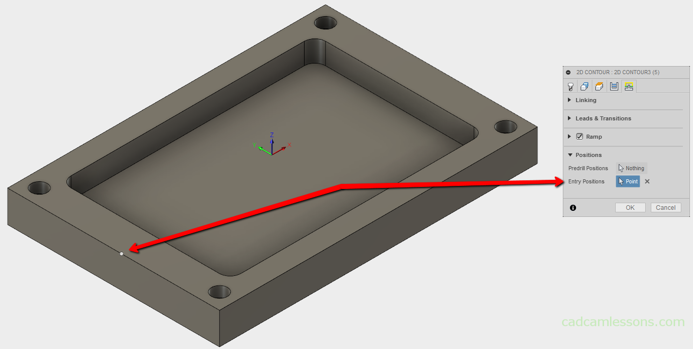
To select the starting point, click on the Nothing, next to Entry Positions and mark the point on the contour where you would like to have the tool in.
After converting the tool path, we get:
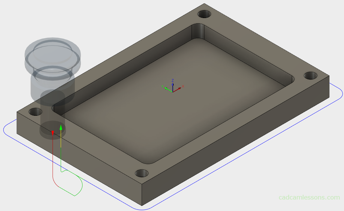
Both options are very useful. Often, an automatically selected starting point is not always good for machining, so it’s a good idea to change it manually.
