Drilling in Alphacam
YouTube: https://youtu.be/aFHxoD0yNpM
In this lesson we will create drilling operation.
From Machine tab select Select Tool command.

At this point, we do not have a drill with a diameter of 9 mm so, let’s choose a drill with a diameter of 10 mm. For demonstration purposes, it does not matter. Later we will define a drill with a diameter of 9 mm.
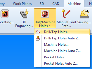
Now, from the Machine tab expand Drill/Machine Holes menu and select Drill/Tap Holes command.
General tab fill in as shown in the drawing below.
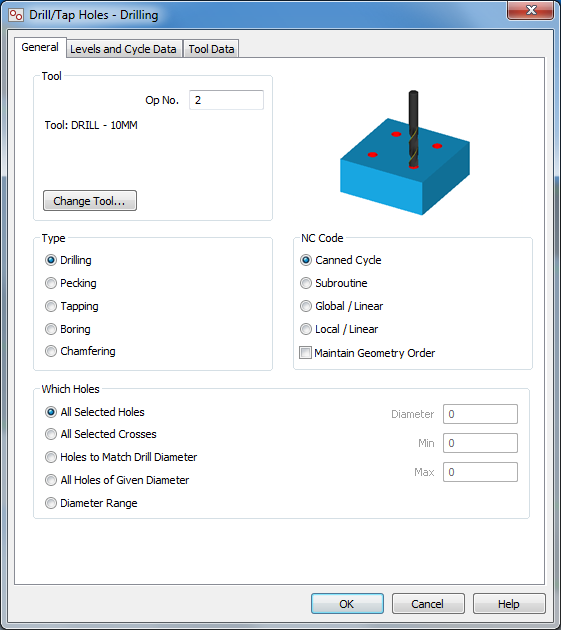
Type Drilling, this is standard drilling (G81).
Select Levels and Cycle Data tab.
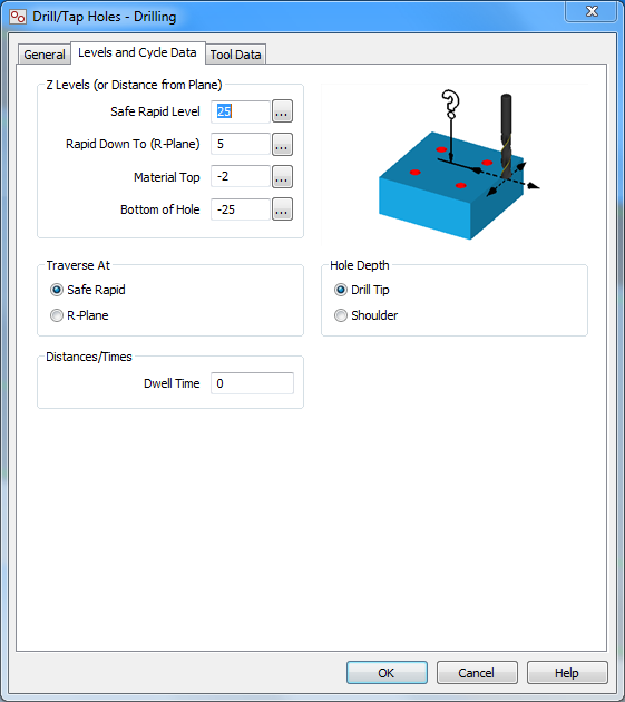
Fill in as shown in the drawing above.
Leave the Tool Data tab with the default values.
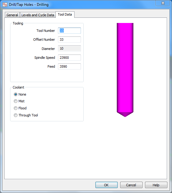
Click OK.
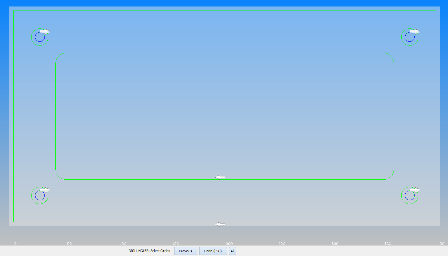
Now, select four small holes. When selecting several holes you do not need to keep the Ctrl key pressed, just click LMB on each hole you want to drill.
Accept by clicking Finish (ESC) button RMB.
A warning window should appear.
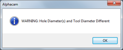
In this case, we do it consciously, so let’s click OK.
Another window with information will appear:
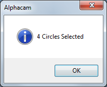
This is information about the number of holes selected. Click OK.
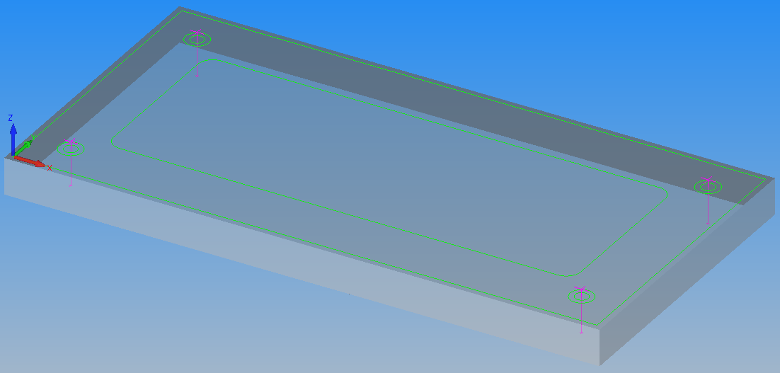
The toolpaths should look like in the picture above.
To explain the next drilling options we need to enable visibility of the rapid movements. This will be a quick tip that will be useful in further work with Alphacam.
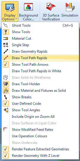
From the View tab expand Display Options menu and select Draw Tool Paths Rapids option.
Now the toolpaths should look like in the picture below.

This is very helpful when you want to check whether the tool (in Z axis) is moving too close to the material or tooling. Remember that these are rapid movements, collision during this movement can be very dangerous.
Subscribe me on YouTube!
Watch the video below!
If you find my tutorials helpful, you can support CADCAMLessons:
https://ko-fi.com/cadcamlessons